General Plane Motion of a Rigid Body
A rigid body undergoes general plane motion when:
- every material point moves in a plane parallel to one fixed plane,
- the body can translate,
- the body can rotate about an axis perpendicular to that plane.
The motion can always be decomposed into:
For any two material points A and B on the same rigid body,
where
is fixed in the body.
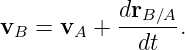
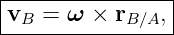
Differentiating gives the fundamental relative-velocity relation
Differentiating again gives the relative-acceleration relation
These two equations are the central kinematic tools for planar rigid body mechanisms.
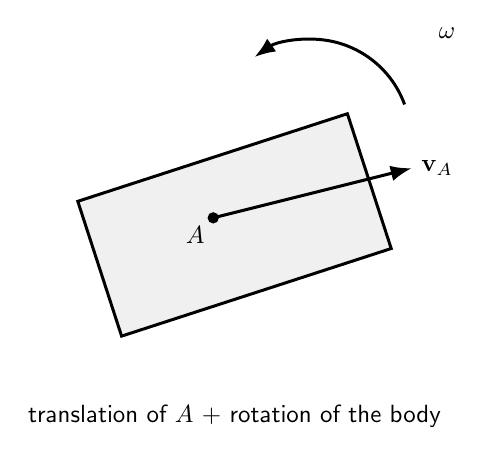
Figure 1. General plane motion combines translation of a chosen reference point with
simultaneous rotation of the rigid body about that point.
1 What makes the motion planar?
Choose the xy plane as the plane of motion.
Then the angular velocity and angular acceleration are perpendicular to that plane:
| ω | = ωez, | (6)
|
| α | = αez. | (7) |
Position, velocity, and acceleration of all material points lie in the xy plane.
Thus the three-dimensional vector equations reduce to a very useful two-dimensional
geometry.
2 The rigid body constraint
For any two material points A and B,
Although
can rotate in an inertial frame, its magnitude remains fixed.
That is the kinematic meaning of rigidity.
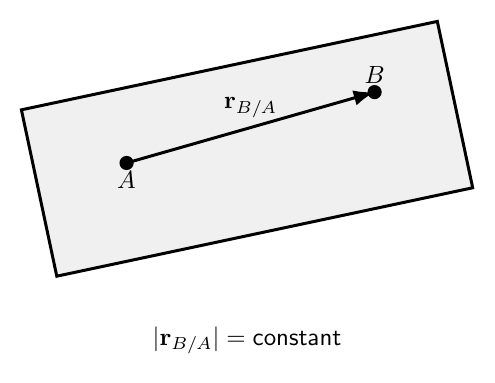
Figure 2. The vector from material point A to material point B rotates with the rigid body, but
its magnitude remains constant.
3 Translation plus rotation about an arbitrary point
The reference point A can be any material point on the rigid body.
Then
The body motion is described by:
- translation of A through rA(t),
- orientation angle 𝜃(t) of the body.
For plane motion, a rigid body has three configuration variables:
These are the three degrees of freedom of an unconstrained rigid body in a plane.
4 Derivation of the relative-velocity relation
Differentiate
Then
Because
is fixed in the rotating body,
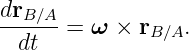
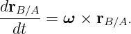
Therefore
The second term is the velocity of B relative to A due to rigid body rotation.
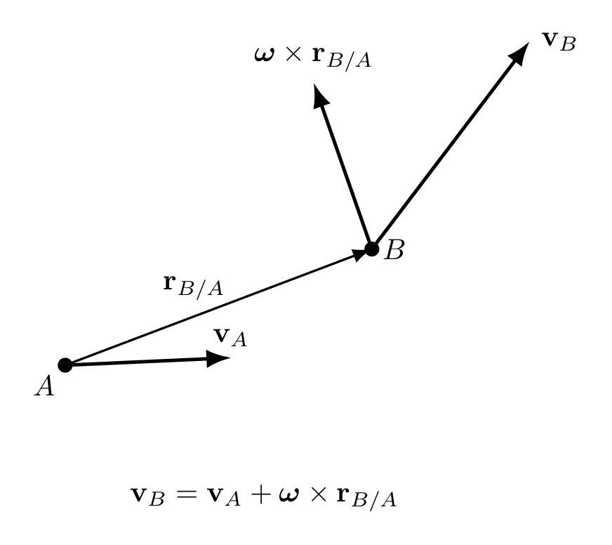
Figure 3. The velocity of point B equals the translational velocity of reference point A plus the
rotational contribution ω × rB∕A.
5 Geometric properties of relative velocity
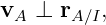
Because
the relative velocity is perpendicular to
Thus
This is an immediate kinematic consequence of rigidity.
If the two points had relative velocity along the line joining them, their separation would be
changing.
6 Planar component form
Let
and
Then
| ω × rB∕A | = ωez × (xex + yey) | (22)
|
| = −ωy ex + ωxey. | (23) |
Therefore
These equations are often convenient for mechanisms.
7 Example 1: velocity of a second point
A rigid bar contains points A and B with
At an instant,
and
Then
| ω × rB∕A | = 2ez × (0.60ex + 0.80ey) | (29)
|
| = −1.60ex + 1.20ey. | (30) |
Thus
| vB | = 3.0ex − 1.60ex + 1.20ey | (31)
|
| = (1.40ex + 1.20ey) m∕s. | (32) |
8 Derivation of the relative-acceleration relation
Differentiate the velocity relation:
Then
| aB | = aA +  × rB∕A + ω × × rB∕A + ω × . . | (34) |
Use
and
Therefore
9 Tangential and normal relative acceleration
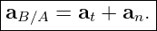
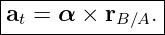
The relative acceleration can be separated into:
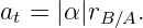
The tangential term is
Its magnitude is
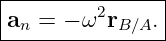
The Normal term is
For planar motion,
Thus the normal component points from B toward A.
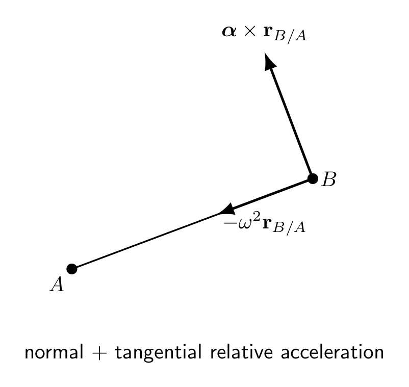
Figure 4. Relative acceleration contains a tangential term perpendicular to rB∕A and a normal
term of magnitude ω2rB∕A directed toward the reference point.
10 Planar acceleration component form
Let
Then
and
Therefore
11 Example 2: acceleration of a second point
Use
Suppose
Tangential relative acceleration:
| α× rB∕A | = 3ez × (0.60ex + 0.80ey) | (52)
|
| = −2.40ex + 1.80ey. | (53) |
Normal relative acceleration:
| − ω2r
B∕A | = −4(0.60ex + 0.80ey) | (54)
|
| = −2.40ex − 3.20ey. | (55) |
Hence
| aB | = (1.0, 0.5) + (−2.4, 1.8) + (−2.4,−3.2) | (56)
|
| = (−3.8ex − 0.9ey) m∕s2. | (57) |
12 Choosing the reference point
Any material point can be used as the reference point.
Common choices include:
- a point with known velocity,
- a point constrained to move along a known path,
- the center of mass,
- a fixed pin,
- a contact point in a rolling problem.
For dynamics and energy, the center of mass is usually especially convenient.
For mechanism kinematics, a constrained endpoint is often better.
13 Special case: pure translation
If
then
If also
then
All points share the same velocity and acceleration.
The body orientation remains constant.
14 Special case: fixed-axis rotation
If point A lies on a fixed axis and is stationary,
Then
and
Thus fixed-axis rotation is a special case of general plane motion.
15 Special case: rolling
For pure rolling on a stationary surface, the contact point has
Therefore at that instant,
This makes the contact point an instantaneous center of zero velocity.
Again, this statement concerns velocity, not necessarily acceleration.
16 Instantaneous center of zero velocity
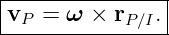
For any planar rigid body motion with
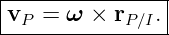
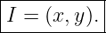
there is generally an instantaneous point I in the plane whose velocity is zero:
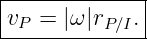
Then for every material point P,
Therefore
At that instant, the velocity field looks exactly like pure rotation about I.
17 Constructing the instantaneous center
If velocity directions are known at two different points A and B:
- draw a line through A perpendicular to vA,
- draw a line through B perpendicular to vB,
- their intersection is the instantaneous center I.
Why?
For instantaneous rotation about I,
and
Thus I must lie on both perpendicular lines.
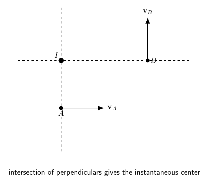
Figure 5. The instantaneous center lies at the intersection of lines drawn through two points
perpendicular to their known velocity directions.
18 Instantaneous center for pure translation
If the body is in pure translation,
All point velocities are parallel and equal.
The perpendicular lines used to locate the instantaneous center are parallel and do not meet at a
finite point.
One may interpret the instantaneous center as lying at infinity.
This is a useful geometric way to see pure translation as a limiting form of planar motion.
19 Example 3: sliding bar
A rigid bar of length L has endpoint A constrained to move horizontally and endpoint B
constrained to move vertically.
Suppose at one instant:
with
The velocity of A is horizontal.
Therefore the line from A to the instantaneous center is vertical.
The velocity of B is vertical.
Therefore the line from B to the instantaneous center is horizontal.
The instantaneous center is at
Thus
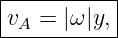
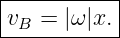
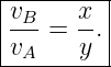
The speed relations are
Hence
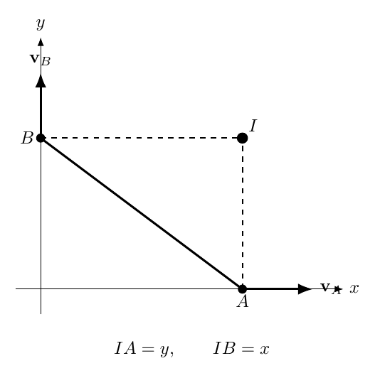
Figure 6. For a bar with one endpoint constrained horizontally and the other vertically, the
instantaneous center is found at the intersection of the vertical through A and the horizontal
through B.
20 Example 4: numerical sliding bar
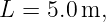
Let
and at one instant
Suppose endpoint A moves to the right at
Then
Therefore
The direction of vB follows from the rigid body rotation sense.
21 Instantaneous center is a velocity concept
The instantaneous center satisfies
at one instant.
It does not generally satisfy
Therefore one generally cannot write
unless the acceleration of I is also properly included.
The correct relation is
The instantaneous center is therefore extremely useful for velocities but must be used cautiously
for accelerations.
22 Velocity field of a planar rigid body
Choose reference point A.
Then
This is an affine velocity field.
Every point velocity is the sum of:
- one common translational velocity,
- a rotational velocity that grows linearly with distance from the reference point.
Differences in point velocities are determined entirely by ω:
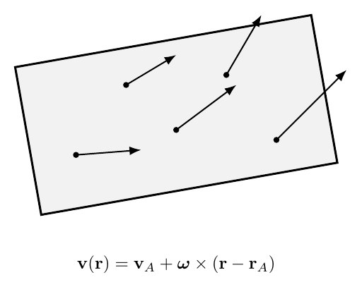
Figure 7. A planar rigid body velocity field is the superposition of one translational velocity and a
rotational field proportional to distance from the chosen reference point.
23 Acceleration field of a planar rigid body
Similarly,
Unlike velocity, acceleration contains:
- a translational contribution,
- a tangential rotational contribution,
- a normal rotational contribution.
The normal term is quadratic in angular speed.
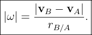
24 Determining angular velocity from two point velocities
From
the relative velocity magnitude is
because the relative velocity is perpendicular to rB∕A.
Thus, if the full velocity vectors are known,
The sign follows from the rotational sense.
25 Determining angular acceleration from two point accelerations
The acceleration difference is
for planar motion.
Project along rB∕A:
Project perpendicular to rB∕A:
Therefore, once ω is known, acceleration data can determine α.
26 Center of mass as reference point
Choosing
gives
and
This form naturally separates translation of the center of mass from rotation about the center of
mass.
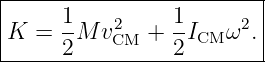
27 Kinetic energy of general plane motion
For a rigid body undergoing general plane motion,
The first term is translational kinetic energy of the center of mass.
The second is rotational kinetic energy about the center of mass.
This decomposition is valid for arbitrary plane motion, not only rolling.
28 Example 5: kinetic energy of a moving bar
A slender bar has
Its center of mass speed is
and its angular speed is
For a slender bar about its center,
Thus
| K | =  (6.0)(3.0)2 + (6.0)(3.0)2 +  (2.0)(4.0)2 (2.0)(4.0)2 | (107)
|
| = 27 + 16 | (108)
|
| = 43 J. | (109) |
29 Constraints in mechanisms
General plane motion often appears in mechanisms.
Examples include:
- connecting rods,
- sliders,
- crank mechanisms,
- robotic links,
- doors and linkages,
- rolling wheels.
Constraints provide known velocity or acceleration directions.
The rigid body relations then connect the constrained points.
A typical workflow is:
- identify the rigid link,
- choose two useful points,
- write the known direction of each constrained velocity,
- use the relative-velocity relation to solve for unknown speeds and ω,
- use the relative-acceleration relation to solve for accelerations and α.
30 Velocity polygons
The equation
can be represented graphically as a vector triangle.
Since
the direction of the relative-velocity vector is known once the body orientation is known.
Velocity polygons were historically important for mechanism design and remain useful for
geometric intuition.
31 Acceleration analysis is harder than velocity analysis
Velocity relative to a reference point has only one rotational term:
Acceleration has two:
and
Thus acceleration analysis requires both:
- angular acceleration,
- angular speed.
A mechanism can have zero angular acceleration at an instant while still having substantial normal
relative acceleration because ω≠0.
32 Example 6: zero angular acceleration does not mean equal accelerations
Suppose a rigid link rotates instantaneously with
and
Then
Its magnitude is
| |aB − aA| | = ω2r
B∕A | (118)
|
| = 25(0.40) | (119)
|
| = 10 m∕s2. | (120) |
Even though
the point accelerations are not equal.
33 Motion taxonomy
The major planar rigid body motions fit into one hierarchy.
- Pure translation:
- Fixed-axis rotation: one point or axis is fixed.
- Rolling Without Slipping: the contact point is an instantaneous center of zero
velocity.
- General plane motion: translation and rotation occur simultaneously without requiring a
permanently fixed point.
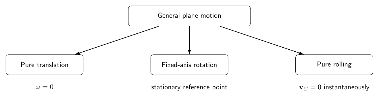
Figure 8. Pure translation, fixed-axis rotation, and pure rolling are special cases within the
broader framework of general plane rigid body motion.
34 Common mistakes
- Treating general plane motion as pure translation.
- Assuming every point on the body has the same velocity.
- Forgetting that vB − vA is perpendicular to rB∕A.
- Using scalar speed addition instead of vector addition.
- Forgetting the normal acceleration term −ω2r
B∕A.
- Assuming α = 0 means all material points have equal acceleration.
- Treating the instantaneous center as a permanently fixed material point.
- Assuming the instantaneous center has zero acceleration because it has zero velocity.
- Using instantaneous-center rotation formulas blindly for acceleration.
- Choosing an awkward reference point when another point has a known velocity or
acceleration.
- Confusing the center of mass with the instantaneous center.
- Forgetting that pure translation corresponds to ω = 0.
- Forgetting that fixed-axis rotation is a special case with a stationary reference point.
- Ignoring constraint directions in mechanism problems.
- Using a velocity relation to infer acceleration without differentiating the rotating
relative-position vector.
35 Practice exercises
- Starting from rB = rA + rB∕A, derive the relative-velocity equation.
- Derive the relative-acceleration equation by differentiating the velocity relation.
- Prove that rB∕A ⋅ (vB − vA) = 0 for a rigid body.
- Derive the planar component equations for vB,x and vB,y.
- Derive the planar component equations for aB,x and aB,y.
- A rigid link has rB∕A = (0.3ex + 0.4ey) m, vA = 2ex m∕s, and ω = 3 rad∕s. Find vB.
- For the previous geometry, let aA = 0, ω = 3 rad∕s, and α = 2 rad∕s2. Find a
B.
- Explain how to construct the instantaneous center from two known velocity directions.
- Explain why the instantaneous center is at infinity for pure translation.
- A 5 m sliding bar has endpoints at (4, 0) and (0, 3) m. If the horizontal endpoint speed
is 6 m/s, find ω and the speed of the vertical endpoint.
- Show why the instantaneous center is generally unsuitable as a fixed pivot for
acceleration calculations.
- Derive the kinetic-energy decomposition K =
 MvCM2 +
  ICMω2.
- A bar has M = 8 kg, L = 3 m, vCM = 2 m/s, and ω = 3 rad/s. Find its total kinetic
energy.
- Show that if α = 0 but ω≠0, two points can still have different accelerations.
- Classify pure translation, fixed-axis rotation, rolling, and general plane motion within
one common rigid body framework.
36 Summary
For any two material points A and B on a planar rigid body,
The relative velocity is perpendicular to the line joining the points:
Acceleration is
For planar motion,
When ω≠0, an instantaneous center of zero velocity can often simplify velocity analysis:
But the instantaneous center is not generally a fixed pivot for acceleration analysis.
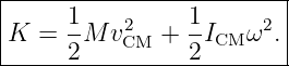
The kinetic energy of general plane motion is
This completes the planar kinematics foundation before M05-09 introduces the inertia tensor and
full three-dimensional Rotational Inertia.
References
References
[1] J. R. Taylor, Classical Mechanics, University Science Books, 2005.
[2] D. Kleppner and R. Kolenkow, An Introduction to Mechanics, 2nd ed., Cambridge
University Press, 2014.
[3] K. R. Symon, Mechanics, 3rd ed., Addison-Wesley, 1971.
[4] OpenStax, University Physics, Volume 1, Rice University, 2016.





























































![|-----------------------------------------------|
a(r) = a + α × (r − r ) + ω × [ω × (r − r )]. |
--------A--------------A-------------------A-----](https://images.physicslibrary.org/cache/objects/1478/make4ht/GeneralPlaneMotionOfARigidBody78x.png)