Free-body diagram
A free-body diagram (FBD) is a diagram in which one chosen object or system is isolated
from its surroundings and every relevant external force acting on that object or system
is represented explicitly. The purpose of an FBD is analytical rather than artistic: it
separates the object of interest from distracting geometric detail and provides the force
model from which Newton’s equations are written. A simple example is given in Figure
1.
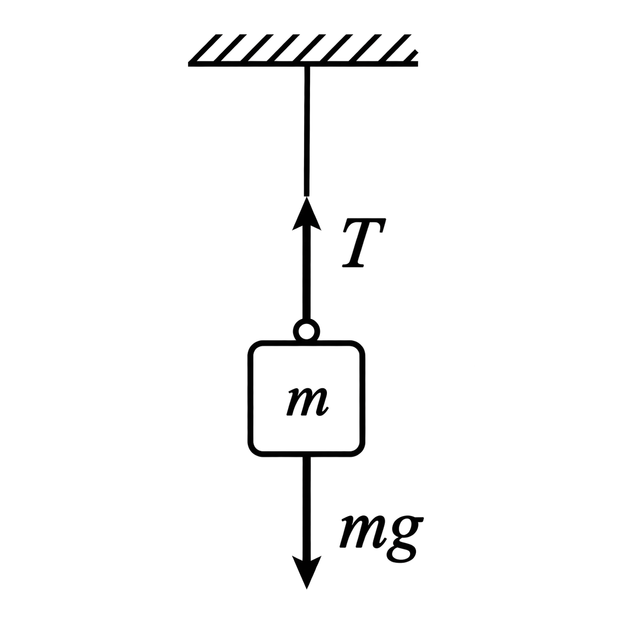
Figure 1. A hanging mass with upward Tension and downward weight.
For a particle or translating rigid body of constant mass,
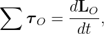
For a rigid body the same diagram also supplies the forces and moment arms used in rotational
dynamics,
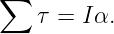
or, in an appropriate fixed-axis special case,
The most important word in the definition is chosen. Before drawing force arrows, one must decide
what object or collection of objects is the system. Whether a force is external or internal depends
on this system boundary.
1 System boundary
A system boundary separates the chosen system from everything else. Forces exerted across the
boundary by the surroundings are external and belong on the free-body diagram. Forces between
parts of a multi-body system are internal and normally do not appear on a free-body diagram of
the whole system.
For example, consider two blocks tied together. If only one block is selected, the string tension
must appear on that block’s FBD. If both blocks are selected together, the tension is internal to
the two-block system and disappears from the system-level FBD. Choosing a useful system
boundary is therefore an important problem-solving strategy.
2 A seven-step construction procedure
A reliable free-body diagram can be constructed by the following sequence.
- Choose the system. State whether the system is one particle, one rigid body, or several
bodies treated together.
- Sketch the isolated body. For particle translation, a point or simple box is usually
sufficient.
- Identify every interaction crossing the system boundary.
- Replace each interaction by a force vector acting on the chosen system.
- Label forces by physical origin, for example mg, N, T, or f.
- Choose coordinate axes that simplify the component equations.
- Write Newton’s equations only after the diagram is complete.
A useful final question is: “For every force arrow, what body in the surroundings exerts this force
on the chosen system?” If that question cannot be answered, the arrow may not represent a real
interaction.
3 Forces commonly appearing on free-body diagrams
Weight
Near the surface of Earth,
directed approximately toward the center of Earth. Weight should not be replaced by components
until coordinates have been selected. On an incline, mg sin 𝜃 and mg cos 𝜃 are components of one
gravitational force, not additional forces.
Normal force
A normal force is a contact force perpendicular to a surface. Its magnitude is not automatically
mg. It must be determined from the equations of motion and the geometry of contact.
Tension
An ideal flexible string or cable pulls along its own direction. In the common ideal model of a
massless string over frictionless massless pulleys, the tension magnitude is the same throughout a
continuous string.
Friction
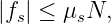
Friction acts tangentially to a contact surface and opposes relative sliding or the tendency to slide.
Static friction satisfies
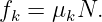
whereas a common kinetic-friction model is
The equality fs = μsN applies only at impending slip.
Spring force
For an ideal linear spring,
where the minus sign indicates a restoring force.
Drag
Common approximations are
for linear drag and
for quadratic drag.
4 Forces are not their components
Suppose an applied force of magnitude F makes angle 𝜃 with the positive x-axis. One may
write
The component terms are a representation of the same force; they are not additional
interactions. The same warning applies to the components of weight on an inclined
plane.
5 Newton’s third law and FBDs
Newton’s third law states
The two forces act on different bodies and therefore do not normally appear together on a
single body’s free-body diagram. For a book on a table, the table’s normal force on the
book and the book’s weight are not a third-law pair because both forces act on the
book.
6 Coordinate choices
Good axes simplify the equations.
- For horizontal surfaces, horizontal and vertical axes are usually natural.
- For inclined planes, axes parallel and perpendicular to the plane are usually best.
- For circular motion, radial and tangential directions are often most useful.
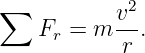
No separate “centripetal force” should be added in an inertial frame. Centripetal force means the
radial component of the net real force,
7 Diagram gallery
7.1 Hanging mass
Figure 1. A hanging mass with upward tension and downward weight.
For a hanging mass attached to a Light string,
7.2 Block on a horizontal surface
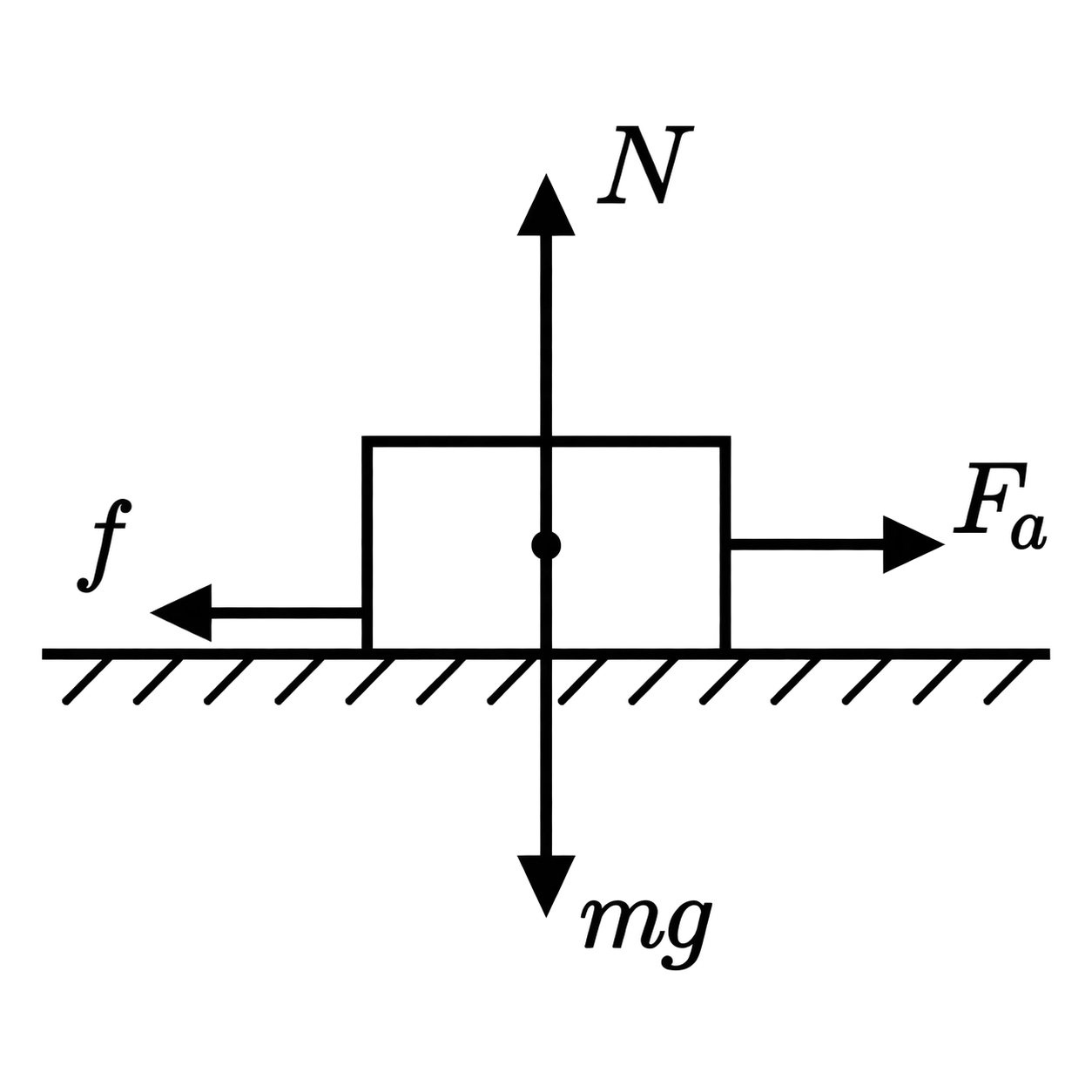
Figure 2. A rough horizontal surface with applied force, friction, normal force, and weight.
If vertical acceleration is zero,
and if the block slides,
7.3 Block on an inclined plane
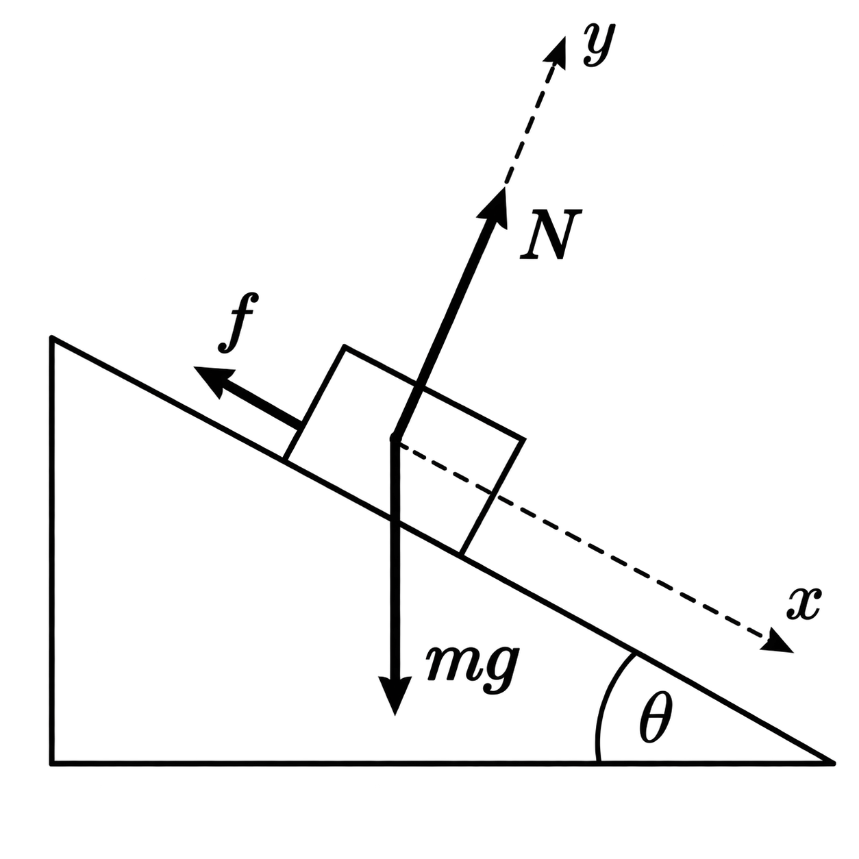
Figure 3. A block on an inclined plane.
With axes parallel and perpendicular to the plane,
7.4 Rough-surface block pulled at an angle
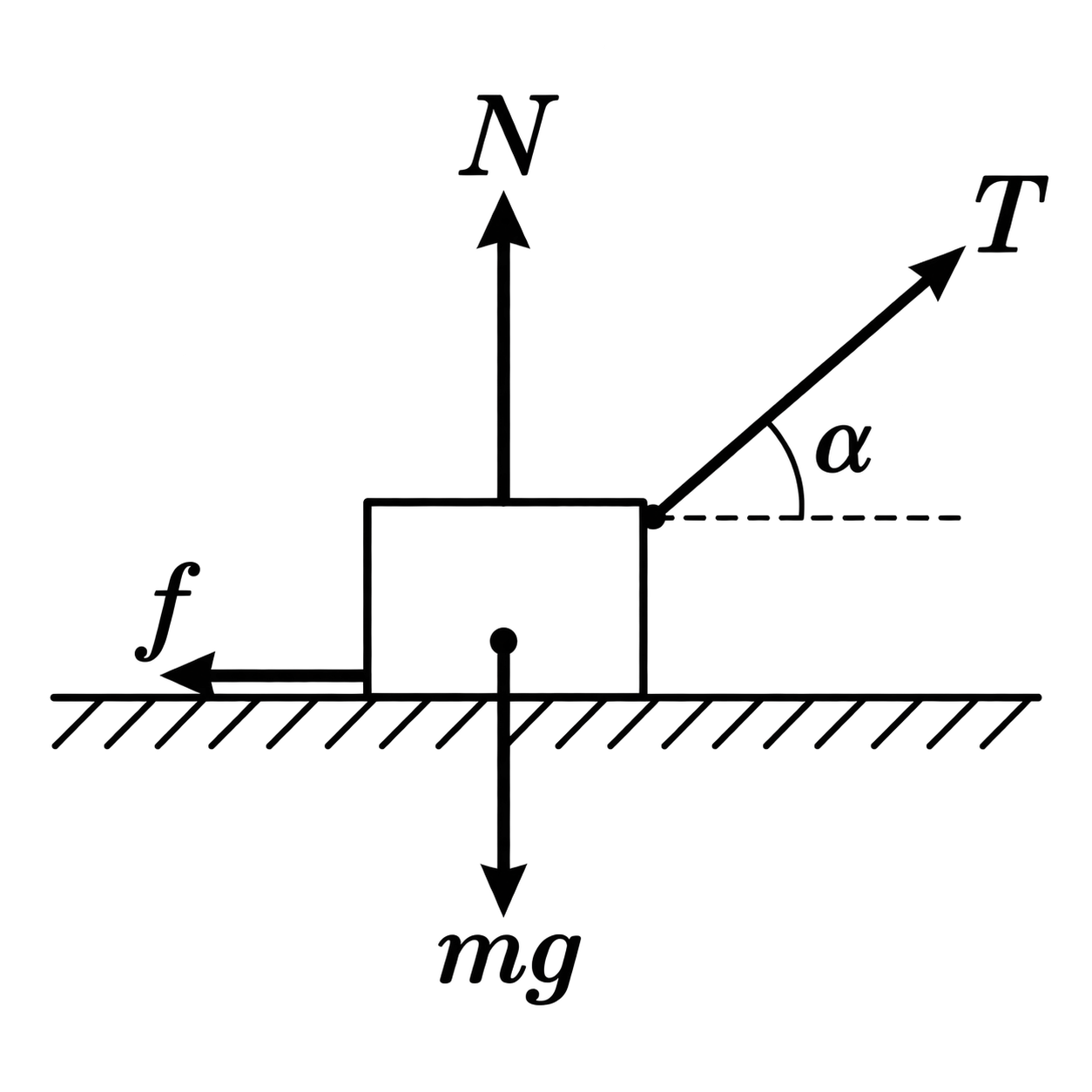
Figure 4. A rough surface block pulled by an oblique force.
The vertical component of the pull changes N and therefore changes the friction magnitude.
7.5 Block against a vertical wall
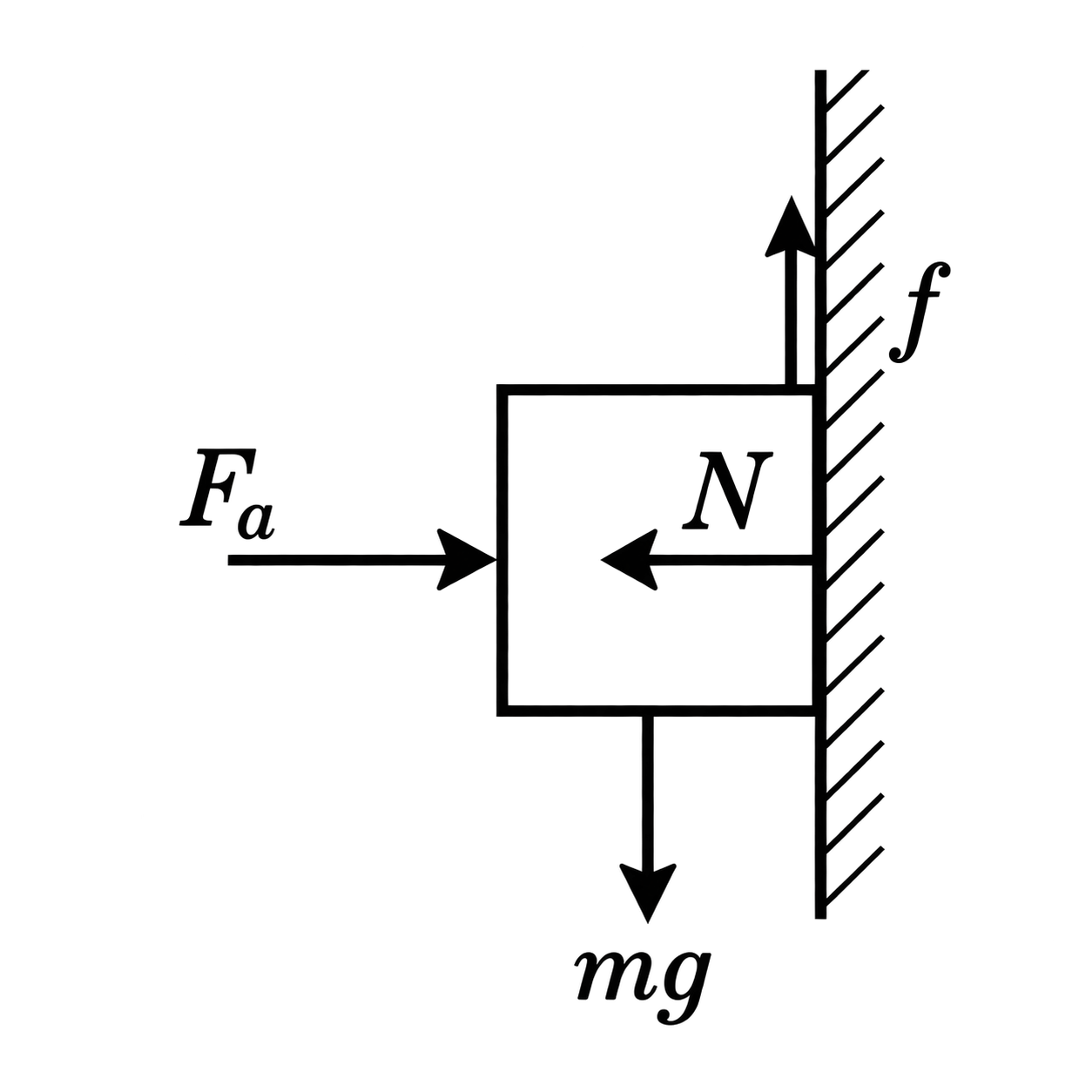
Figure 5. A block held against a vertical wall.
If the block tends to slide downward, static friction acts upward.
7.6 Mass-spring system
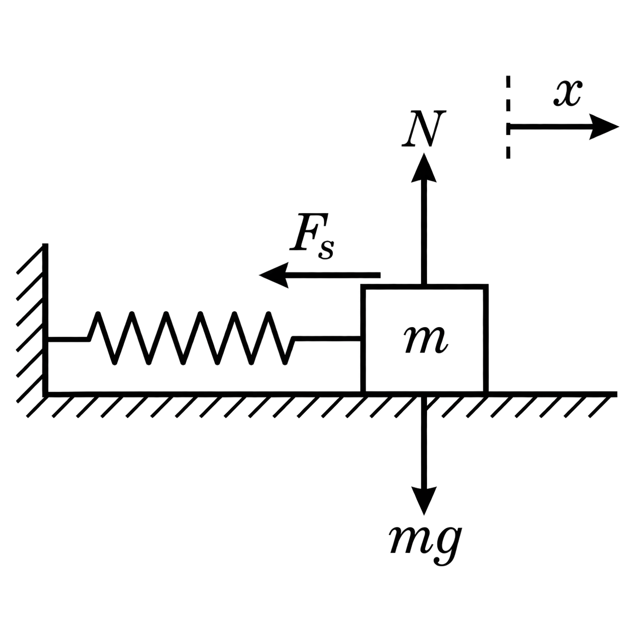
Figure 6. A horizontal mass-spring system.
For an ideal spring,
7.7 Pendulum bob
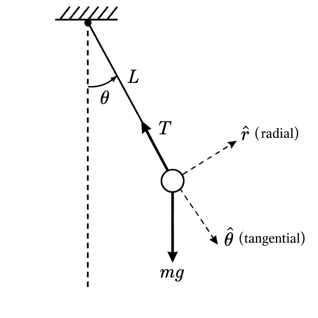
Figure 7. A pendulum bob with tension and weight.
Radial and tangential directions are especially convenient for pendulum dynamics.
7.8 Banked curve

Figure 8. A vehicle represented on a banked curve.
The normal force need not be vertical; its horizontal component can contribute to centripetal
acceleration.
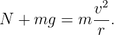
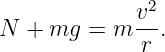
7.9 Loop-the-loop at the top

Figure 9. At the top of an inside loop, both N and mg point toward the center.
The radial equation is
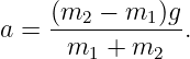
7.10 Atwood machine
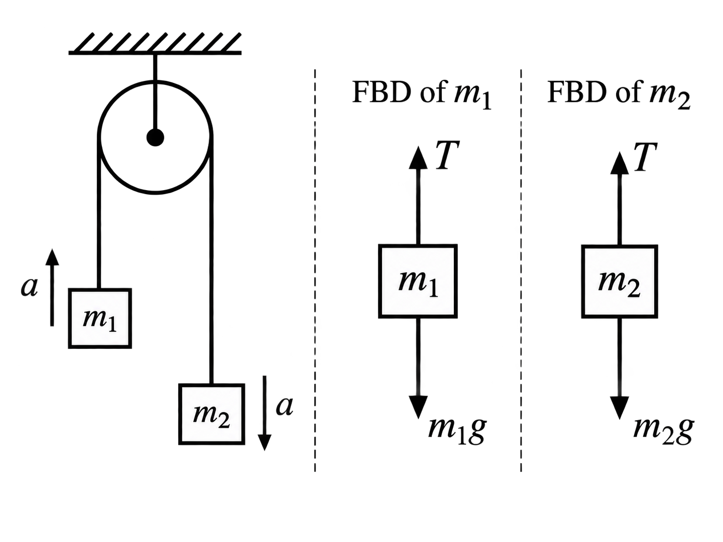
Figure 10. An Atwood-machine system sketch and separate FBDs for the two masses.
For m2 > m1 and an ideal string and pulley,
so
8 Worked examples
Example 1: horizontal pull
A 5.0 kg block is pulled horizontally by a 20 N force on a frictionless horizontal surface. The FBD
gives
Hence
Example 2: pull at an angle
A 10 kg block is pulled with force 50 N at 30∘ above horizontal. The vertical equation
is
so
If kinetic friction is present, its magnitude is μkN, showing why the vertical component of an
oblique pull changes the horizontal friction force.
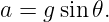
Example 3: frictionless incline
For a block on a frictionless incline of angle 𝜃,
so
Example 4: rough incline
If a block slides down a rough incline,
therefore
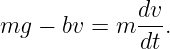
Example 5: terminal speed with linear drag
For downward positive direction,
At terminal speed, dv∕dt = 0, hence
Example 6: car at the top of a loop
At the top of an inside loop, inward is downward. The real inward forces are N and
mg:
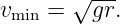
The minimum speed for contact occurs when N = 0,
9 Common mistakes
- Omitting an external interaction.
- Adding a force that acts on another body rather than the chosen body.
- Drawing both members of a Newton’s-third-law pair on one body’s FBD.
- Drawing both a force and its components as separate forces.
- Treating “centripetal force” as an extra force.
- Assuming N = mg without checking the vertical or normal equation.
- Assuming static friction always equals μsN.
- Choosing axes that make the geometry unnecessarily complicated.
10 Non-inertial frames
The diagrams above assume an inertial frame. If Newton’s second law is written directly in
an accelerating or rotating frame, inertial-force terms such as centrifugal and Coriolis
forces may be introduced. They should be labeled explicitly as frame-dependent inertial
terms rather than being confused with physical interactions such as gravity or contact
forces.
11 Bridge to analytical mechanics
Free-body diagrams are central to Newtonian mechanics because they make individual forces
explicit. In Lagrangian mechanics, ideal constraint forces can often be eliminated by
choosing generalized coordinates adapted to the constraints. The conceptual progression is
therefore
Free-body-diagram reasoning remains valuable even when the final equations are obtained
from a variational principle because it clarifies the physical interactions and constraint
assumptions.
References
[1] J. Moore and contributors, Mechanics Map, Engineering LibreTexts. Creative
Commons Attribution–ShareAlike 4.0. Mechanics Map
[2] T. Weideman, UCD Physics 9A – Classical Mechanics, Physics LibreTexts. Creative
Commons Attribution–ShareAlike 4.0. UCD Physics 9A
Unless otherwise noted, this PhysicsLibrary entry is intended for release under the Creative
Commons Attribution–ShareAlike 4.0 International license.