E00: Foundations of Electricity and Electrical Measurement
A PhysicsLibrary mini-lecture roadmap connecting elementary electricity to the EDL home
electrodynamics laboratory.
1 Why a separate theory series?
In EDL01, we connect meters to circuits, infer resistances from measurements, observe RC
transients, and learn to use function generators and oscilloscopes. Those are experiments. Before
performing them, we must understand what the instruments measure and why the measurements
sometimes change the circuit.
The E-series is the theory companion to the EDL experimental series. It is not a second laboratory
series and is not a substitute for a full course in electromagnetic fields. Each mini-lecture derives
the minimum necessary physics, makes clear the assumptions behind a circuit model, and supplies
a simple numerical prediction that can be tested in EDL.
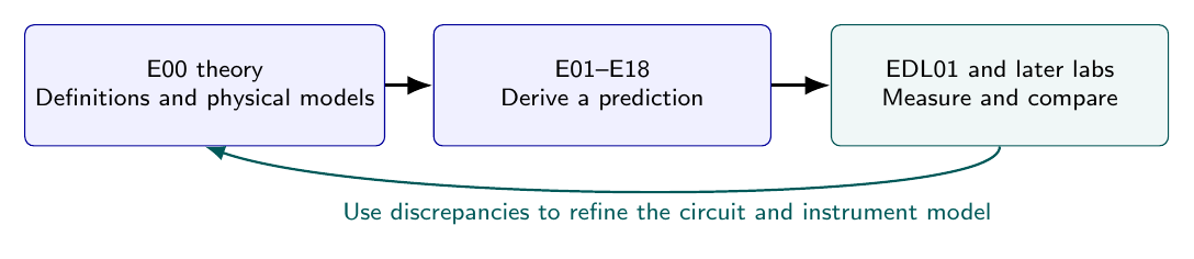
Figure 1. E-series lectures explain the model, EDL experiments test the predictions, and
discrepancies motivate better models of the instrument and circuit.
Learning principles
- Begin with a physical quantity and its SI unit.
- Explain the operational meaning: how could we measure it?
- Derive the governing equation from a more fundamental statement.
- State the approximations needed to use the equation in a circuit.
- work a small numerical problem, including a dimensional check.
- Identify a measurable quantity in EDL01 or a later EDL laboratory.
- Close with conceptual questions and a short worked exercise.
The sequence is deliberately compact. An individual E01–E18 article should normally be a focused,
self-contained mini-lecture rather than a long survey. Where useful, an E##E1 companion can hold
worked exercises.
2 A short conceptual preview
The first four lectures develop the basic quantities in a useful order. Electric Charge q has units of
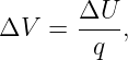
coulombs. A potential difference is energy per unit charge,
for the change of potential energy of a specified test charge in an electrostatic situation. Electric
current is the rate of charge transfer,
In a component that behaves as an ohmic resistor,
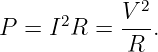
The rate of electrical energy transfer at its terminals is
For an ohmic resistor absorbing Power, these become
These relations are neither interchangeable definitions nor universally valid laws for arbitrary
devices. Charge conservation is general, while V = IR is a constitutive model that is appropriate
for an ohmic component under specified conditions.
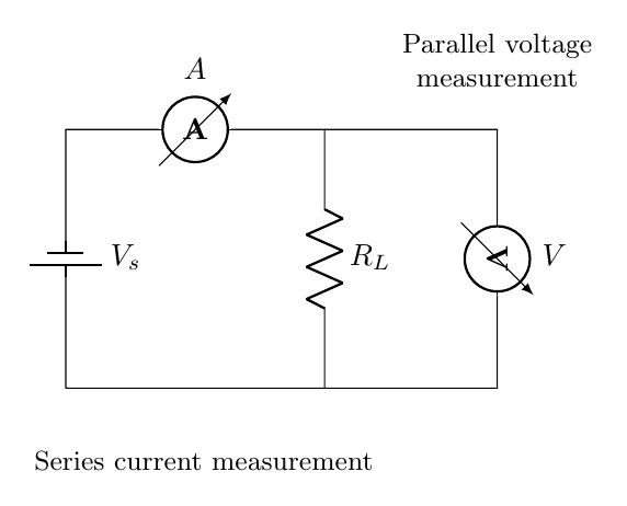
Figure 2. A low-voltage circuit. The ammeter is inserted in series to measure branch current,
while the voltmeter is placed across the load to measure the terminal potential difference.
3 Part I: Physical foundations (E01–E04)
E01: Electric Charge, Electric Potential, and Voltage
Core questions. What is charge? How is potential difference related to energy per unit charge?
Why does a voltmeter measure a difference between two points rather than an absolute
voltage?
Main ideas. Charge polarity and conservation; coulomb and volt; electric potential energy;
electrostatic potential difference; conventional voltage polarity; battery terminal voltage and
electromotive force as a practical source concept. Briefly explain that potential differences arise
from electric fields and that a battery maintains a potential difference using nonelectrostatic
processes.
Key relations:
Worked example. Find the energy change for moving a charge through a specified potential
difference, with signs interpreted carefully.
EDL connection. Read voltage across a battery and across a resistor.
E02: Electric Current and Conservation of Charge
Core questions. What moves in a Conductor? How does conventional current differ from electron
drift? Why must the sum of steady-state currents at a junction vanish?
Main ideas. Current I = dq∕dt, ampere as coulomb per second, current direction, drift motion,
charge accumulation, and conservation of charge. Derive the junction rule from a charge balance on
a small region.
Key relations:
Worked example. Convert a measured current and elapsed time to transferred charge, then
balance currents at a three-branch node.
EDL connection. Predict and measure series current.
E03: Electrical Resistance and Ohm’s Law
Core questions. What opposes charge flow? Why is resistance a material and geometry-dependent
property? When is V = IR a useful model?
Main ideas. Ohmic versus nonohmic behavior; volt-ampere plots; resistivity, length,
cross-sectional area; temperature dependence at an introductory level; resistance measurement.
Key relations:
Worked example. Compute the slope of a measured V versus I line and interpret it as
resistance.
EDL connection. EDL01 Ohm’s-law measurements.
E04: Electrical Power, Energy, and Resistive Heating
Core questions. Where does electrical energy go? Why do resistor power ratings matter? Why
does increasing voltage sometimes produce a large increase in heating?
Main ideas. Power as rate of energy transfer; passive sign convention; dissipative heating; resistor
ratings and thermal limits.
Key relations:
Worked example. Calculate the power in a resistor and select a rating with appropriate
margin.
EDL connection. Low-voltage component and instrument safety.
4 Part II: Elementary circuit models (E05–E08)
E05: Circuit Models, Nodes, Branches, and Ground
Core questions. What is a node? What does a circuit schematic leave out? Why does “ground”
not automatically mean Earth?
Main ideas. Ideal wires, nodes, branches, loops, reference potential, open circuits, short circuits,
and the lumped-circuit assumption. Distinguish a local 0-V reference from protective Earth and
from instrument chassis connections.
Worked example. Redraw a breadboard circuit as a node-labeled schematic and identify which
points have the same ideal potential.
EDL connection. Breadboard wiring and oscilloscope-ground checks.
E06: Series and Parallel Circuits, Voltage and Current Dividers
Core questions. Why do series resistors carry the same current? Why do parallel resistors have
the same potential difference? How does a voltage divider predict a measured node
voltage?
Main ideas. Equivalent resistance; division of current and voltage; loading introduced
qualitatively.
Key relations:
Worked example. Predict a divider output and the change when a known load is
connected.
EDL connection. EDL01 voltage-divider loading.
E07: Kirchhoff’s Laws and Elementary Circuit Analysis
Core questions. How does charge conservation constrain branch currents? Why must potential
changes sum to zero around a closed loop in the usual lumped-circuit approximation?
Main ideas. Kirchhoff current law; Kirchhoff voltage law; sign conventions; nodal equations; one-
and two-loop examples. Explain that lumped-loop voltage sums must be treated with care when
appreciable time-varying magnetic flux threads the loop.
Key relations:
Worked example. Solve a two-branch resistive network using one node equation.
EDL connection. Predict the current and voltage at every node in EDL01 before placing an
instrument.
E08: Real Voltage Sources, Internal Resistance, and Thevenin Models
Core questions. Why can a source voltage fall when loaded? What information do two load
measurements provide? Why might a function generator display a different voltage from the
oscilloscope?
Main ideas. Open-circuit voltage; source resistance; terminal voltage; load lines; Thevenin and
Norton equivalents for linear circuits; source resistance inference from measurements.
Key relations:
Worked example. Infer an unknown output resistance using two known loads and their measured
terminal voltages.
EDL connection. EDL01 function-generator source resistance.
5 Part III: Electrical measurement (E09–E13)
E09: How Voltmeters, Ammeters, and Ohmmeters Work
Core questions. Why is a voltmeter connected in parallel and an ammeter in series? What do the
meters do to the original circuit? Why must an ohmmeter be used on a de-energized
component?
Main ideas. Input resistance of voltage mode; current-sense resistance and burden voltage;
current-range fuses; internally generated test current in resistance mode; auto-ranging and
specifications.
Worked example. Predict the current with and without a known series meter resistance.
EDL connection. Every DMM measurement in EDL01.
E10: Measurement Loading and Instrument Input Impedance
Core questions. Can a voltmeter alter the voltage it reads? Why is an oscilloscope probe more
than a large resistance? What conditions make an instrument nearly noninvasive?
Main ideas. Divider loading by finite Rm; input capacitance; frequency-dependent input
impedance; difference between indicated voltage and the circuit’s unloaded voltage; error as a
function of source resistance.
Key relations:
Worked example. Compare readings for different meter input resistances and infer the meter
input resistance from its loading effect.
EDL connection. EDL01 loaded divider and oscilloscope probe loading.
E11: Accuracy, Precision, Resolution, Calibration, and Uncertainty
Core questions. What does a displayed digit mean? How does a percentage-of-reading
specification differ from a digit specification? Why is a repeatable measurement not necessarily
accurate?
Main ideas. Random variation, systematic effects, correction, resolution, calibration,
repeatability, type A and Type B uncertainty evaluation; simple uncertainty propagation;
line-fitting for V = RI.
Key relation (uncorrelated standard uncertainties):
Worked example. Report an inferred resistance with a defensible uncertainty and
unit.
EDL connection. Uncertainty statements in every experimental report. NIST guidance provides
the framework for uncertainty terminology.
E12: Function Generators and Electrical Waveform Measurements
Core questions. What is an amplitude? What is peak-to-peak voltage? What is offset? What is
the meaning of a 50-ohm source setting?
Main ideas. DC offset, sine and square waves, peak and peak-to- peak amplitude, output
resistance, high-impedance versus matched loads, waveform frequency, duty cycle, rise
time.
Key relations:
Worked example. Predict the observed voltage when a 50-ohm output is connected to a
high-impedance measurement input instead of a 50-ohm load. Always check the generator’s display
convention.
EDL connection. EDL01 function-generator experiments.
E13: Oscilloscopes, Probes, Bandwidth, and Grounding
Core questions. What does the oscilloscope measure at its input? Why do 1X and 10X probes
behave differently? Why must we identify a probe’s ground connection before attaching
it?
Main ideas. Volts/div and seconds/div; triggering; input resistance and capacitance; probe
attenuation; compensation; bandwidth; input coupling; common-ground versus isolated
measurements; grounding safety.
Worked example. Explain why a high-impedance probe changes the RC time constant less than
an input with much larger capacitance.
EDL connection. EDL01 probe loading, transient observation, and grounding.
6 Part IV: Time dependence and signals (E14–E18)
E14: Capacitors, Charge Storage, and Electric Field Energy
Core questions. Why can voltage across a capacitor not change instantaneously without
unbounded current in the ideal circuit model? Where is the stored energy located?
Main ideas. Capacitance, dielectric concept, charge and voltage, current through a capacitor,
ideal capacitor energy, and the connection to electric fields.
Key relations:
Worked example. Estimate the charge and energy stored in a capacitor at a given low
voltage.
EDL connection. EDL01 RC circuit and later electrostatics labs.
E15: RC Charging, Discharging, and Time Constants
Core questions. Where does the exponential time dependence come from? Why does a
time constant have the dimensions of seconds? How can a transient reveal an unknown
capacitance?
Main ideas. KCL and the capacitor current relation; first-order differential equation; initial and
final conditions; charging and discharging; exponential fitting.
Key relations:
for charging from zero through a resistor from an ideal step source. Worked example. Determine
τ from the time to reach 1 − e−1 ≃ 0.632 of the final voltage.
EDL connection. EDL01 RC charging and discharging.
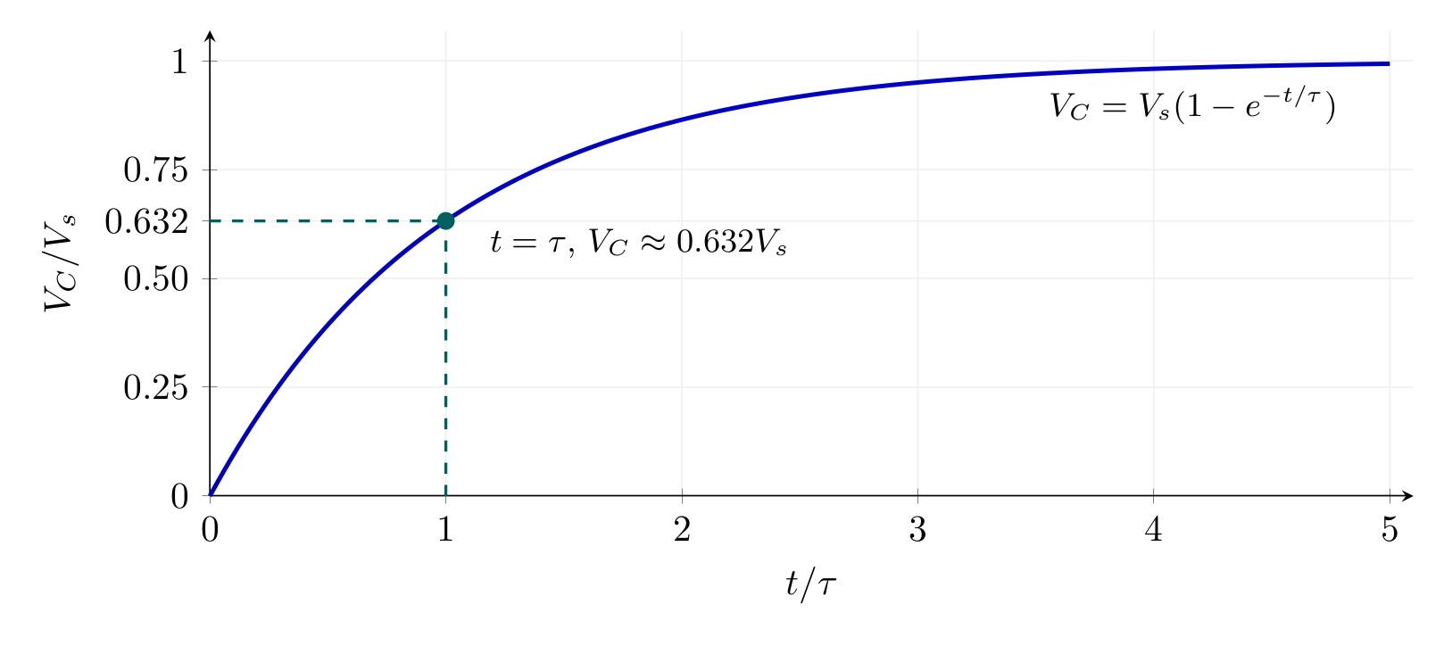
Figure 3. An ideal RC step response reaches about 63.2 percent of its final value after one time
constant. The time constant is inferred from measured time and voltage, not from the graph
alone.
E16: Sinusoidal Voltages, Frequency, Phase, and RMS
Core questions. How do amplitude, frequency, and phase describe a sinusoid? What does a
true-RMS meter report? Why is the RMS value not generally the same as the average
voltage?
Main ideas. Frequency and period; angular frequency; phase shifts; root-mean-square definition;
average power for a resistor.
Key relations:
for a pure sinusoid without DC offset. Worked example. Convert a sinusoidal peak-to-peak
voltage to RMS and use it to calculate power in a resistor.
EDL connection. Function-generator and oscilloscope cross-checks.
E17: Impedance, Phasors, and RC Frequency Response
Core questions. Why does a capacitor respond differently at low and high frequency? How do
complex numbers simplify steady-state sinusoidal circuits?
Main ideas. phasor notation, impedance, RC low-pass and high-pass filters, gain and phase, 3-dB
cutoff at an introductory level. Cross-reference the PhysicsLibrary Fourier and Laplace series for
extensions.
Key relations:
for a simple RC low-pass with output across the capacitor. Worked example. Predict the
amplitude ratio at the cutoff frequency fc = 1∕(2πRC).
EDL connection. AC response, probe loading, and later frequency-domain experiments.
E18: Electrical Noise, Bandwidth, Sampling, and Measurement Limits
Core questions. Why does a stationary resistor produce a fluctuating voltage? How does
bandwidth affect measured noise? Why is a digital measurement limited by sample rate and
resolution?
Main ideas. Johnson-Nyquist noise in its applicable classical regime; RMS noise and
bandwidth; averaging; basic sampling and aliasing; ADC quantization; practical noise
floors.
Key relations:
for the open-circuit thermal-noise voltage of an ideal resistor measured over an equivalent
noise bandwidth B in the classical white-noise regime. Worked example. Estimate
how much RMS noise changes when measurement bandwidth increases by a factor of
four.
EDL connection. Later noise-versus-temperature and carrier-to-noise-ratio experiments.
7 Capstone example: Why a voltmeter changes a divider
To show how the articles fit together, consider a 5.0-V ideal source and two 100 kΩ resistors in
series. Without a meter,
A voltmeter with a 1.0 MΩ input resistance is then connected across the lower resistor.
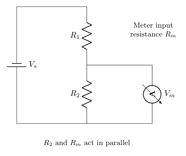
Figure 4. The voltage meter is electrically in parallel with the lower resistor. Its finite input
resistance changes the effective divider ratio and therefore the voltage it indicates.
The effective lower resistance is
| Rp | = R2 ∥ Rm | (23)
|
| =  | (24)
|
| = 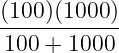 kΩ | (25)
|
| ≃ 90.91 kΩ. | (26) |
The measured voltage becomes
The meter reports a voltage approximately 4.76 percent below the unloaded value. This is
not simply a defect in numerical precision. It is a change to the circuit caused by the
measurement.
The example requires the ideas developed across E05–E10 and directly predicts an observation in
EDL01. A typical 10 MΩ input meter would load the same divider less; the actual input resistance
must be checked for the selected instrument and range.
8 Dependency map to EDL01
- EDL01 Ohm’s-law measurements: E01–E04, E09, E11.
- EDL01 loaded voltage divider: E05–E07, E09–E11.
- EDL01 generator source-resistance inference: E06–E08, E12.
- EDL01 probe loading: E08, E10, E13, E17.
- EDL01 RC transient: E02, E07, E14–E16.
- EDL01 scope grounding and safety: E04–E05, E13.
- Later EDL noise measurements: E11, E16–E18.
- Later EDL electrostatics: E01 and E14, followed by the more detailed field theory
in the existing EM series.
The sequence also offers convenient entry points. A learner can start EDL01’s basic Ohm’s-law
experiment after E01–E04 and E09, then return for the later lectures before attempting generator,
oscilloscope, or transient measurements. It is not necessary to complete all 18 lectures before doing
any laboratory work.
9 Standard template for each E-series mini-lecture
Every article should contain the following elements.
- Motivating observation. A physical question that the next EDL experiment can
answer.
- Definitions and units. Explicit statements of what is being defined and what is being
modeled.
- Physical model. Schematic, sign convention, assumptions, and limits of validity.
- Derivation. Short algebraic or calculus steps without unexplained formula jumps.
- Worked prediction. A numerical example with reasonable component values and a
units check.
- Measurement interpretation. What the instrument actually reads and how it might
perturb the circuit.
- Misconceptions. At least two common conceptual pitfalls.
- Exercises and complete solutions. A few short problems, with longer problem sets
in an optional E##E1 companion.
- Cross-references. Link the relevant EDL experiment and advanced EM, FS, or LT
article where appropriate.
10 Safety scope for the series
All initial demonstrations should use current-limited, isolated, low-voltage DC sources. Never
suggest connecting a breadboard, handheld meter in current mode, or an ordinary grounded
oscilloscope directly to mains power. A current meter must be inserted in series, not across a
voltage source. Resistance measurements should be made with the circuit de-energized and with
capacitors safely discharged. Many bench oscilloscope ground clips are tied to protective Earth;
verify the actual instrument before connecting them. Select component wattage and wire current
ratings conservatively.
11 Suggested publication order
Publish E00 first, followed by E01–E04 so that every basic EDL01 result has a physical
interpretation. Continue with E05–E10 to support circuit analysis and measurement loading. E11
then provides the uncertainty framework. E12–E13 support function-generator and oscilloscope
use. Finally E14–E18 establish transient, AC, and noise measurements. This order avoids requiring
phasors or Maxwell’s Equations for basic voltage measurements, but provides a path toward
both.
12 What comes after E18?
The E series ends at the point where a reader can confidently use common instruments to measure
simple DC and AC circuits and recognize the limitations of the measurement. More detailed
field-theory questions remain with the EM series, advanced time-dependent analysis with the LT
and FS series, and experimental applications with the EDL series.
References and further reading
References
[1] OpenStax, University Physics, Volume 2, sections on electric current, resistance,
circuits, electrical measuring instruments, and RC circuits, Rice University.
[2] National Institute of Standards and Technology, Guidelines for Evaluating and
Expressing the Uncertainty of NIST Measurement Results, Technical Note 1297.
[3] P. Horowitz and W. Hill, The Art of Electronics, sections on elementary circuits and
measurement practice.
[4] D. J. Griffiths, Introduction to Electrodynamics, sections on electrostatic potential,
current, charge conservation, and capacitance.