Free-Body Diagrams
A Free-body diagram, usually abbreviated FBD, is a simplified force model of one chosen body or
system. The body is isolated conceptually from its surroundings, and every external
interaction with the surroundings is replaced by a force vector acting on the isolated
system.
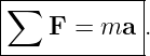
A good FBD is not merely a picture of the physical scene. It is the bridge between the physical
situation and Newton’s second law:
The main skill is therefore not drawing arrows. It is deciding which body is being modeled,
identifying every interaction that acts on that body, excluding forces that act on other bodies, and
translating the resulting vector diagram into equations.

Figure 1. A free-body diagram is produced by isolating a chosen system, replacing its external
interactions by force vectors, and then resolving the force sum into useful components.
1 A free-body diagram is a model
Suppose a crate rests on a floor while a person pulls on it with a rope. The physical scene
may contain the floor, rope, person, crate, Earth, and many geometric details. If the
crate is the chosen system, the FBD contains only the external forces acting on the
crate.
Typical forces might include
the normal force from the floor,
the pull from the rope,
and, when appropriate, friction,
The person, floor, rope, and Earth themselves do not appear as separate objects on the FBD.
Their interactions with the crate are represented by forces.
2 Step 1: choose the system boundary
Before drawing any force, state what object or collection of objects is being analyzed.
The system boundary determines which forces are external and which interactions are
internal.
For a single particle or rigid body, the system boundary encloses that one object. For a multi-body
system, several objects may be enclosed together.
This choice can change the force equation. A contact force between two blocks is external when
either block is analyzed alone, but internal when both blocks are included in one combined
system.
3 Step 2: identify interactions
A force should correspond to a physical interaction. A reliable way to build an FBD is to ask what
objects in the environment interact with the chosen system.
Common interactions include:
- Earth acting gravitationally on a mass;
- a surface acting through a normal force and possibly friction;
- a string or cable acting through Tension;
- a spring acting through a spring force;
- a fluid acting through drag or buoyancy;
- another body acting through contact or a long-range interaction.
M02-03 treats these common force laws in detail. In the present article, the emphasis is the
diagramming procedure.
4 Step 3: draw only forces acting on the chosen body
Every force arrow on a free-body diagram must answer the question:
What external object exerts this force on the chosen system?
This criterion prevents one of the most common mistakes: placing both members of a
Newton-third-law pair on one FBD.
Consider a book resting on a table. The table exerts an upward normal force on the
book,
The book exerts the opposite force on the table,
The first belongs on the book’s FBD. The second belongs on the table’s FBD.

Figure 2. A Newton-third-law pair acts on two different bodies. Only the forces acting on the
selected body belong on that body’s free-body diagram.
5 Step 4: choose coordinates after the forces are identified
Coordinate axes are mathematical choices, not physical forces. They should be selected to simplify
the component equations.
For a block on an incline, it is often convenient to choose
and
Then the weight vector can be resolved into components relative to those axes.

Figure 3. Draw the actual forces first. Afterward, choose axes that simplify the geometry and
resolve forces such as the weight into components. Components are not additional forces.
A useful rule is:
Draw forces first; resolve components second.
If the weight is decomposed into mg sin 𝜃 and mg cos 𝜃, those quantities are components
of the single force mg. They should not be drawn as extra forces in addition to the
weight.
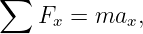
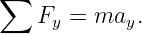
6 Step 5: write Newton’s second-law equations
Once the FBD is complete, Newton’s second law is written in the chosen coordinate system. In two
dimensions,
and
The FBD should make every term in these equations traceable to one physical force
vector.
If the object is in equilibrium,
so
If the object accelerates, the component equations contain the corresponding nonzero acceleration
components.
7 What does not belong on an FBD
The following quantities should generally not appear as force arrows on a standard free-body
diagram:
- velocity v;
- acceleration a;
- displacement or position vectors;
- the object’s future path;
- force components drawn in addition to the original force;
- a Newton-third-law partner force that acts on another body;
- quantities such as ma, which represent the result of the force sum rather than a new
physical force.
Acceleration may be shown separately beside the FBD as a kinematic annotation if doing so aids
the solution, but it should not be mistaken for a force.
8 Force labels should identify the interaction
A label such as F1 may be sufficient in a short algebra problem, but descriptive labels are usually
safer. Examples include
and
For problems involving several bodies, source-target notation can remove ambiguity. For
example,
means the force acting on A due to B.
9 At least ten recurring FBD archetypes
Many introductory dynamics problems reduce to a small number of recurring diagram structures.
The force laws differ from problem to problem, but the system-selection procedure is the
same.
- Object in free fall. If air resistance is neglected, the only force is the weight mg.
- Object resting on a horizontal support. Typical forces are weight downward and
normal force upward.
- Block pushed or pulled on a horizontal surface. Add the applied force and, if
present, friction.
- Block on an inclined plane. Weight remains vertical; the normal force is
perpendicular to the surface; friction, when present, is tangent to the surface.
- Hanging object. Typical forces are weight downward and one or more tensions
directed along supporting strings or cables.
- Mass attached to a spring. Include weight and support/contact forces as needed,
plus the spring interaction along the spring axis.
- Elevator passenger or scale problem. The passenger’s FBD usually contains
weight and the support normal force. The relation between them depends on vertical
acceleration.
- Object moving in a horizontal circle. Draw the real forces that produce the inward
net force. Do not add a separate “centripetal force.”
- Object moving in a vertical circle. Weight and tension or normal force may both
have radial components whose contributions vary around the path.
- Two connected particles. Draw a separate FBD for each particle when the internal
tension or contact force is an unknown of interest.
- Two-body combined system. Enclose both bodies if an internal interaction can be
eliminated from the system force sum.
- Object moving through a fluid. Depending on the model, include weight, buoyancy,
drag, and any support forces.
The important habit is to recognize these as modeling patterns rather than formulas to
memorize.
10 System boundaries and internal forces
Suppose two blocks A and B push on one another while an external force acts on the pair. If
the blocks are analyzed separately, the contact interaction appears on both FBDs as a
Newton-third-law pair.
If the combined system A + B is analyzed, the interaction between A and B is internal. The pair
cancels when the two body equations are added.

Figure 4. Internal interactions appear on separate body diagrams but cancel from the force sum
when both interacting bodies are enclosed within one combined system boundary.
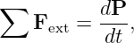
This leads naturally to the system form
where P is the total momentum of the chosen system.
11 Normal force is not automatically equal to weight
A frequent mistake is to write
whenever an object touches a surface. This equality is true only when the vertical force balance
happens to require it.
For example, if a person in an elevator accelerates upward,
so
If the elevator accelerates downward, the normal force is smaller than mg. Thus the FBD should
be drawn before any relation such as N = mg is assumed.
12 Friction direction and magnitude
Friction acts tangent to the contact surface and opposes relative sliding or the tendency to
slide.
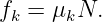
For kinetic friction,
For static friction, however,
Static friction is therefore not automatically equal to μsN. The required value follows from the
force equations until the limiting value is reached.
Detailed friction modeling is developed in M02-07.
13 Worked example 1: book at rest on a table
A 3.0 kg book rests on a horizontal table. Construct the FBD and find the normal
force.
The book interacts with Earth and the table. Its forces are
downward and
upward.
Choose upward as positive. Because the book is at rest,
Newton’s second law gives
Therefore
The equality N = mg follows from the FBD and the zero vertical acceleration; it is not a general
property of normal forces.
14 Worked example 2: horizontal pull with kinetic friction
A 12 kg crate slides to the right on a horizontal floor. A horizontal force of 50 N pulls the
crate to the right, while kinetic friction of magnitude 18 N acts to the left. Find the
acceleration.
The FBD contains four forces: weight, normal force, the applied pull, and kinetic friction.
In the vertical direction,
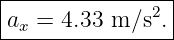
In the horizontal direction,
Hence
The acceleration is not drawn as a force arrow; it is the result of the net-force equation.
15 Worked example 3: pull at an upward angle
A 20 kg crate is pulled across a horizontal floor by a 100 N force directed 30∘ above the horizontal.
Ignore friction. Find the horizontal acceleration and the normal force.
The applied force has components
and
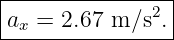
Horizontal motion gives
so
There is no vertical acceleration, so
Thus
The upward component of the applied force reduces the required normal force.
16 Worked example 4: hanging lamp supported by two cables
A lamp of mass 10 kg hangs at rest from two identical cables, each making 40∘ above the
horizontal. Find the tension in each cable.
The lamp’s FBD contains its weight and two cable tensions. By symmetry the horizontal tension
components cancel.
Vertical equilibrium gives
Therefore
The two tension vectors are different forces acting on the lamp even though their magnitudes are
equal.
17 Worked example 5: elevator passenger
A 70 kg passenger stands on a scale in an elevator accelerating upward at 1.5 m∕s2. What force
does the scale exert on the passenger?
The passenger’s FBD contains weight downward and the scale’s normal force upward.
Choose upward as positive:
Therefore
Thus
The scale reading is larger than the passenger’s weight because the net force must point
upward.
18 Worked example 6: two blocks as separate and combined systems
Blocks A and B of masses 2.0 kg and 3.0 kg rest on a frictionless horizontal surface. A horizontal
external force of 20 N pushes block B to the right while B remains in contact with
A.
First choose the combined system A + B. The contact force between the blocks is internal,
so
Hence
Now isolate block A. Its only horizontal force is the contact force from B:
Therefore
The partner force on B is 8.0 N to the left. It appears on B’s FBD, not on A’s.
19 Common mistakes
- Drawing forces that act on other bodies.
- Drawing acceleration or velocity as though they were forces.
- Adding a separate “centripetal force” instead of identifying the real inward forces.
- Assuming N = mg before writing the vertical force equation.
- Assuming fs = μsN for every static-friction problem.
- Drawing both a force and its components as separate forces.
- Choosing a system boundary only after equations have already been written.
- Forgetting a long-range interaction such as gravity simply because there is no physical
contact.
- Using the direction of motion to determine the direction of the net force. Force direction
is related to acceleration, not directly to velocity.
- Treating an internal force as external when analyzing a combined multi-body system.
20 Practice problems
- A 5.0 kg box rests on a horizontal floor. Draw its FBD and find the normal force.
- A 4.0 kg block on a horizontal floor is pulled rightward by 18 N while friction of 6 N
acts leftward. Find the acceleration.
- A 15 kg crate is pulled horizontally by 60 N on a frictionless floor. Draw the FBD and
find ax.
- A 10 kg crate is pulled by an 80 N force at 25∘ above horizontal. The floor is frictionless.
Find the normal force and horizontal acceleration.
- A 6.0 kg object hangs motionless from one vertical rope. Draw the FBD and find the
rope tension.
- A 12 kg traffic Light hangs symmetrically from two cables, each 35∘ above horizontal.
Find the tension in each cable.
- A 65 kg person stands on a scale in an elevator accelerating downward at 2.0 m∕s2.
Find the scale force.
- A 2.5 kg block slides down a frictionless 30∘ incline. Draw the FBD and find the
acceleration along the incline and the normal force.
- A 4.0 kg block rests on a horizontal surface. A horizontal 10 N force is applied, and
static friction is sufficient to keep the block at rest. What is the actual static-friction
force?
- A CAR moves at constant speed around a level circular track. Name the real horizontal
force that can provide the inward acceleration and explain why “centripetal force”
should not be drawn as an additional force.
- Two blocks of masses 3.0 kg and 5.0 kg are pushed together on a frictionless floor by
a 32 N horizontal force applied to the 5.0 kg block. Find the system acceleration and
the contact force on the 3.0 kg block.
- A book rests on a table. Identify the Newton-third-law partner to the table’s normal
force on the book. Does that partner belong on the book’s FBD?
- A falling object experiences both weight downward and drag upward. At one instant
the drag magnitude equals one-half the weight. What is the direction of the acceleration
and what is its magnitude in terms of g?
- Explain why the components mg sin 𝜃 and mg cos 𝜃 on an incline are not additional
forces distinct from the weight mg.
21 Answer check
- N = 49.1 N.
- a = (18 − 6)∕4 = 3.0 m∕s2 rightward.
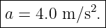
- a = 60∕15 = 4.0 m∕s2 rightward.
- N = mg − 80 sin 25∘ ≃ 64.3 N; a
x = 80 cos 25∘∕10 ≃ 7.25 m∕s2.
- T = mg = 58.9 N.
- T = mg∕(2 sin 35∘) ≃ 102.6 N.
- N = m(g − a) = 65(9.81 − 2.0) ≃ 508 N.
- a = g sin 30∘ = 4.91 m∕s2 down the plane; N = mg cos 30∘ ≃ 21.2 N.
- fs = 10 N opposite the applied force.
- Static friction from the road can provide the inward horizontal force; “centripetal”
describes the required net inward force, not an extra interaction.
- a = 32∕(3 + 5) = 4.0 m∕s2; contact force on the 3.0 kg block is 12 N.
- The partner is the normal force exerted by the book on the table; it acts on the table
and therefore is not on the book’s FBD.
- Net force is downward with magnitude mg∕2, so a = g∕2 downward.
- They are projections of the single weight vector onto chosen coordinate axes.
22 Summary
A free-body diagram is a force model of a chosen system. The reliable procedure is:
- choose the body or system;
- identify its external interactions;
- draw one force vector for each interaction;
- exclude forces that act on other bodies;
- choose convenient axes;
- resolve vectors into components;
- apply Newton’s second law component by component.
The diagram should make the equation
physically transparent. A correct FBD is therefore one of the central modeling tools of Newtonian
mechanics.
References
[1] J. Moore et al., Mechanics Map, sections on free-body diagrams and particle
dynamics, CC BY-SA 4.0.
[2] University of California, Davis, Physics 9A classical mechanics materials, Newtonian
force modeling and applications, CC BY-SA 4.0.
[3] PhysicsLibrary, M02-01, Newton’s Laws of Motion.

![[parent]](https://images.physicslibrary.org/images/uparrow.png)