EDL02: Electrostatics, Charge, Induction, and an Electrometer
Laboratory purpose. We will construct a foil-leaf electroscope, use it to distinguish electrostatic
polarization from charge transfer, produce a persistent net charge by induction, and
investigate how a conducting shield changes the response of a sensitive charge detector. The
experiment develops the basic physics required for the quantitative companions EDL02E1 and
EDL02E2.
A primary lesson is that three statements are not equivalent:
- a nearby object produces an Electric Field;
- charge within the detector redistributes;
- the detector has acquired a nonzero net charge.
The first two can occur without the third. A second lesson is that the movement of an electroscope
leaf is not, by itself, a calibrated reading of charge in coulombs or electric field in volts per
meter.
1 Learning objectives and physical questions
By the end of the experiment, the reader should be able to
- distinguish excess electrons from positive charge left by a deficit of electrons;
- apply conservation of charge to rubbing, contact, and grounding;
- explain attraction of a neutral Conductor by polarization;
- predict the sign left on a conductor after the ground-assisted induction sequence;
- build an electroscope and distinguish a transient from a retained charge;
- measure a repeatable relative leaf-deflection response;
- test the shielding effect of an enclosing conductor;
- identify errors caused by humidity, leakage, drafts, and nearby objects;
- distinguish an electroscope from a calibrated electrometer.
The experimental sequence is deliberately qualitative first, and only semiquantitative
afterward. We want clear identification of what quantity the instrument can actually
report.
2 Charge, force, and field
2.1 Net charge and charge conservation
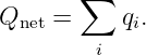
An object contains both positive and negative charge. Its net charge is the algebraic
sum
Charge is measured in coulombs ( ). A negative net charge usually means an excess of electrons.
A positive net charge usually means that some electrons have been removed. In ordinary
solid conductors, it is chiefly electrons that move; the positive ion cores stay in the
material.
For an electrically isolated system,
contact electrification can move electrons between materials without creating charge from
nothing. If electrons carrying charge  move from A to B, then
 and
 . Their net charge changes sum to zero. The microscopic charging
mechanism of rubbed surfaces may depend on the materials, surface chemistry, and
environment. Do not assign a charge sign to a particular rubbing pair without a reliable
reference.
2.2 Coulomb force and electric field
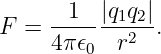
For ideal point charges separated by  , the force magnitude is
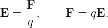
Equal signs repel and opposite signs attract. The electric field is force per positive test
charge:
The field direction is defined by the force on a positive test charge. A negative test charge
experiences force in the opposite direction.
2.3 Electric potential and the sign of energy
In electrostatics, the field is conservative:
For a charge  , its potential energy is
 , and therefore
A charged detector does not simply move toward lower  in every case. Positive charges tend to
be forced toward lower potential; negative charges toward higher potential. In both cases, the
electrostatic force points toward decreasing potential energy along the force direction. This
distinction also helps explain the direction of electron motion inside a conductor while it
polarizes.
3 Conductors, insulators, and polarization
A conductor permits charge to redistribute relatively freely. An insulator strongly inhibits
long-range motion of charge under ordinary laboratory conditions. A dielectric insulator can still
polarize through small displacements of bound charge.
In electrostatic equilibrium, for an ideal conductor,
If a negatively charged rod approaches an isolated, neutral metal sphere, electrons redistribute
away from the rod. One side becomes relatively positive and the far side relatively negative, while
the total charge of the sphere remains zero.
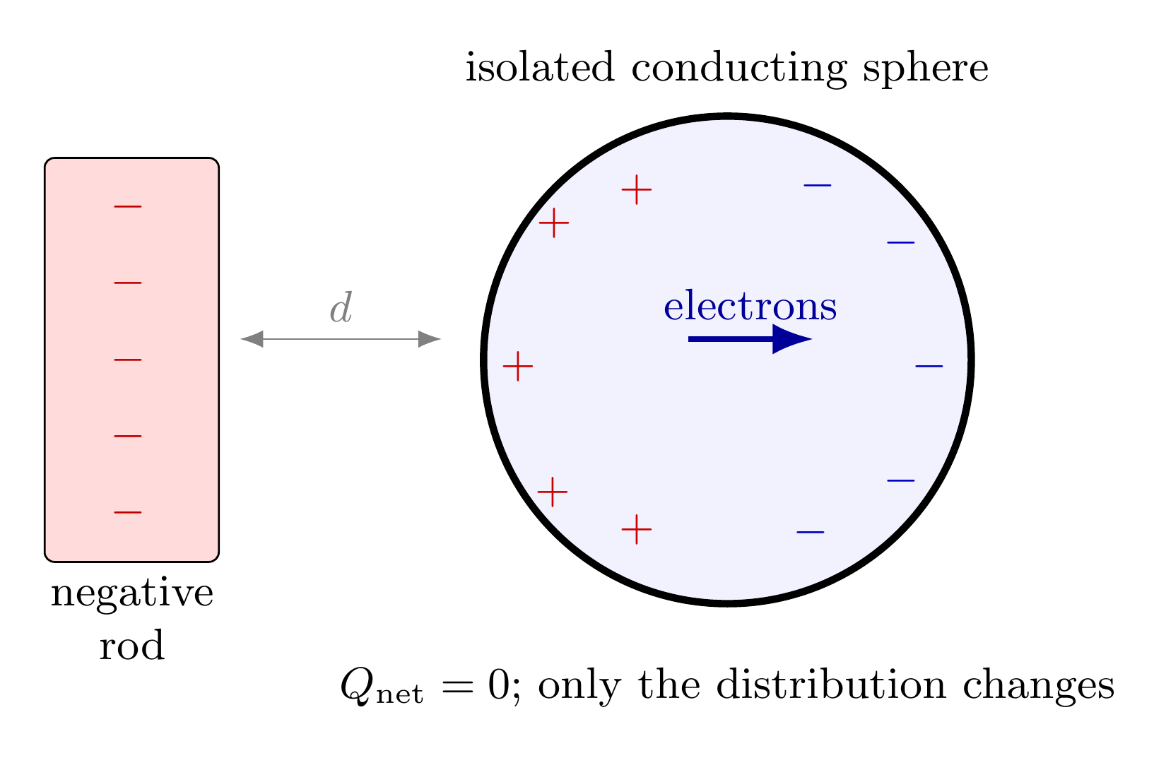
Figure 1. An external charged rod polarizes a neutral conductor. The local positive and negative
regions are not new charge created in the conductor, and the net charge remains zero.
Why can a charged rod attract an initially neutral object? Opposite charge induced on the near
side of the object is closer to the rod than the like-sign charge on the far side. For suitable
geometries, the near-side attraction dominates. Consequently, attraction by itself does not
determine the sign of the unknown charge.
4 The three basic charging processes
4.1 Charging by contact
A charged object physically touches a conducting detector. Charge can flow across the point of
contact. The final amount depends on the initial charges and the combined geometry and
capacitance of the two conductors. Two geometrically identical conductors that touch and then
separate in a symmetric arrangement may share charge nearly equally. Two unlike conductors
generally need not do so.
4.2 Polarization without contact
A charged rod approaches a neutral isolated detector without touching it. The charges already in
the detector rearrange, and the leaf may separate. If the rod is then removed and nothing has
transferred charge, the initial state should be approximately restored.
4.3 Charging by induction using ground
A conductor can acquire net charge without touching the charged rod. The order of operations is
essential. For a negatively charged rod:
- Begin with a neutral, isolated electroscope.
- Bring the negative rod near its metal cap without touching.
- While keeping the rod in place, briefly connect the cap to ground. Some electrons leave
the electroscope through the connection.
- Disconnect the ground before moving the rod.
- Remove the rod. The electroscope retains positive net charge.
For a positively charged rod, electrons instead enter from ground, and the remaining electroscope
charge is negative.
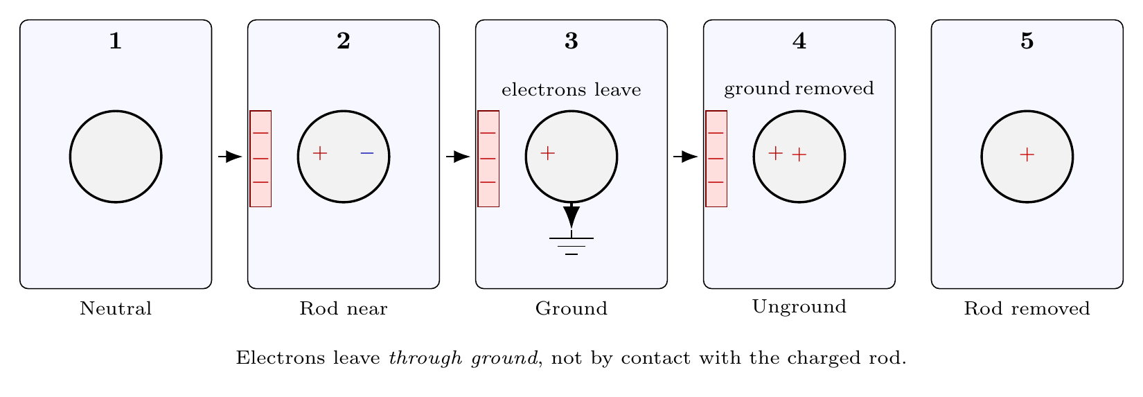
Figure 2. Ground-assisted induction with a negative rod. The wire or finger is removed before the
rod; otherwise the residual net charge may be discharged.
The word ground describes an electrical connection to a large charge reservoir or an effective
reference. A finger often supplies a large-enough charge reservoir for a classroom electroscope, but
this is not equivalent to a verified protective-earth connection. For this battery-free experiment, do
not connect the electroscope to an outlet, oscilloscope ground clip, or mains ground
terminal.
5 Build the mechanical electroscope
5.1 Equipment and purchasing options
Basic household track:
- A clear plastic jar or storage container with a lid, preferably roughly 15 to 25 cm high;
an insulating jar is convenient.
- Straight copper wire or a large metal paper clip, roughly 15 to 25 cm long, to form the
central conductor.
- Aluminum foil for two light leaves and the top terminal.
- A small nonconducting washer, cork, or rubber grommet to hold the wire in the lid
without electrically joining it to a metal cap.
- Adhesive tape, scissors, a ruler, and a sheet of graph paper.
- Plastic rod, comb, or balloon and a clean wool or microfiber cloth.
- A stable table, smartphone camera, and a lamp for recording leaf motion; a hygrometer
is useful but not required.
Optional purchases or upgrades:
- Commercial coated pith balls and a second insulating support for the Coulomb-law
companion EDL02E2.
- Transparent acrylic enclosure and precision millimeter grid for improved repeatability.
- A triboelectric demonstration rod and compatible rubbing cloth; actual charging sign
must be established experimentally.
- EDL02E1’s JFET detector and DMM for a separate electronic response measurement.
It is not a substitute for a calibrated electrostatic field meter.
The home-built electroscope does not require a precision scale, a function generator, or an
oscilloscope. If the leaf is too heavy, experiment with very thin foil strips before purchasing a
commercial instrument.
5.2 Construction
- Wash and dry the container. Clean surfaces minimize leakage paths.
- Make a small opening in the plastic lid, using an appropriate hand tool and eye
protection. Avoid drilling glass.
- Insert the metal wire through a nonconducting support. Make a smooth metal terminal
on the outside and a small hook inside the jar.
- Cut two nearly identical foil leaves, each approximately 4 mm × 25 mm as a trial size.
- Suspend the leaves from the same conductive hook so both receive charge. Their free
lengths should match, and they should be able to swing without rubbing the container
or each other.
- Secure a vertical millimeter scale behind the leaves, leaving enough distance so it cannot
touch the central conductor.
- Close the lid. Confirm that the top electrode is electrically connected to the internal
hook, but insulated from the outer enclosure.
- Gently touch the top electrode to discharge the apparatus and photograph its
zero-charge reference configuration.
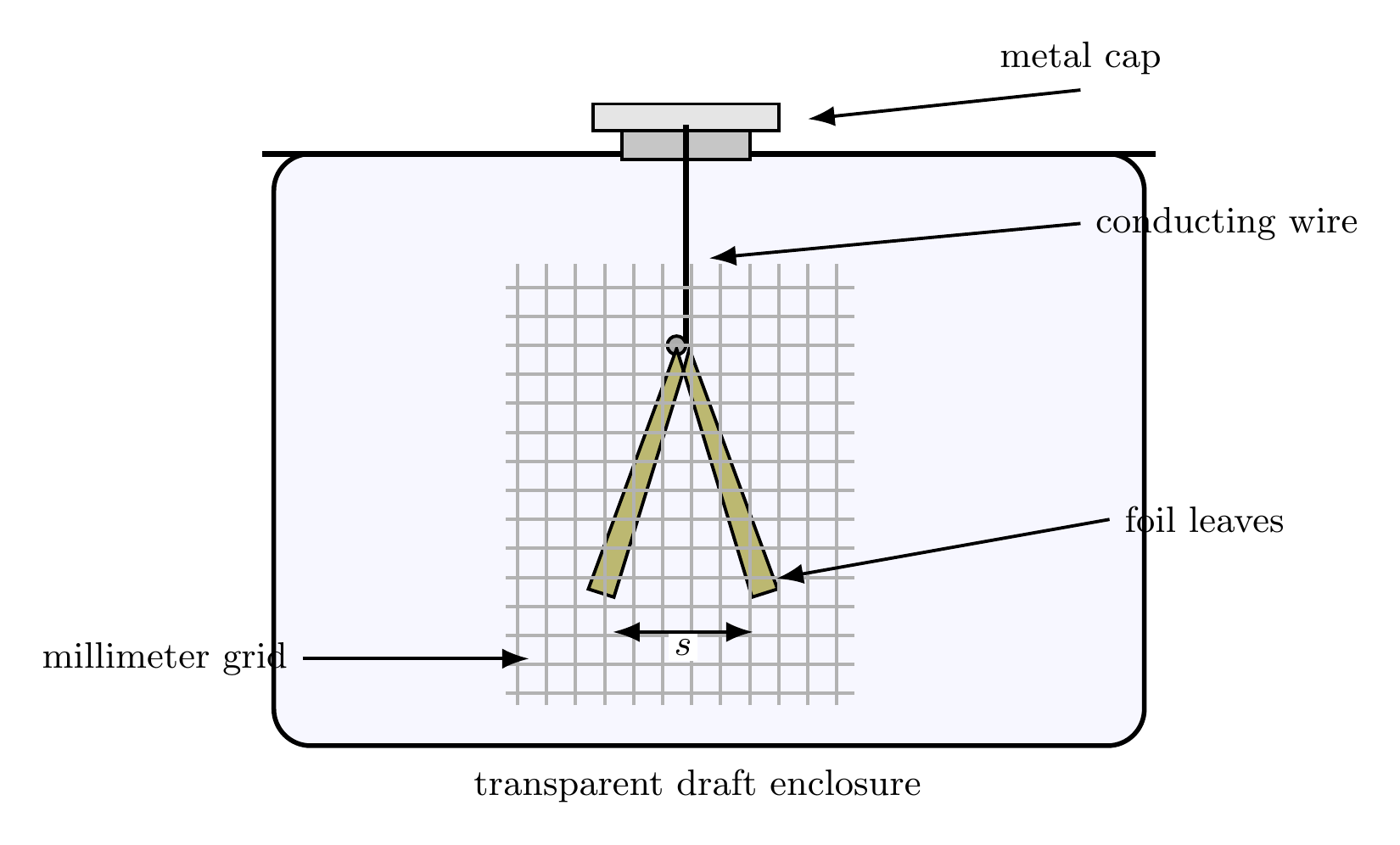
Figure 3. Home-built leaf electroscope. A conductive terminal feeds a pair of foil leaves inside a
draft-reducing transparent enclosure; the background scale provides relative deflection readings.
5.3 Why the leaves separate
If both leaves acquire charge of the same sign, mutual repulsion tends to spread them apart. Their
Weight and bending resistance oppose this movement. The equilibrium configuration depends
on leaf shape, flexibility, charge distribution, and surroundings. Even for nominally
identical leaves, a measured angle is not automatically proportional to  ,
 , or
 .
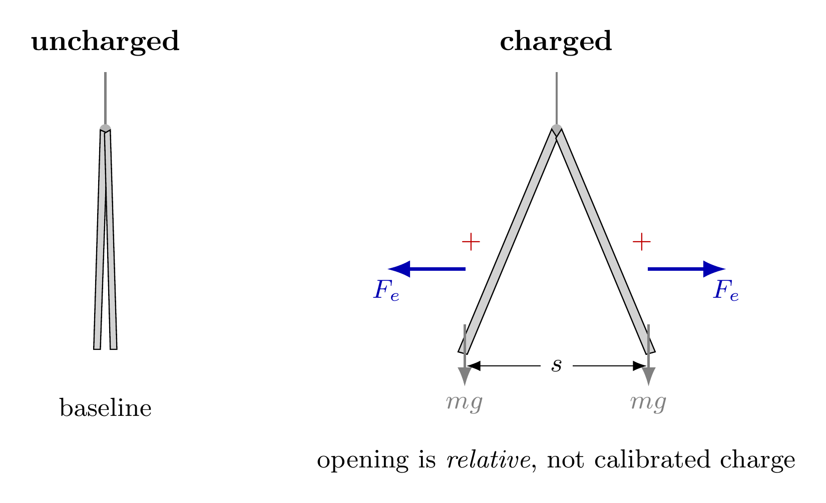
Figure 4. Qualitative leaf-force balance. Electric repulsion tends to open the leaves, while gravity
and mechanical stiffness oppose the motion. The relation between angle and charge requires
calibration and a mechanical model.
6 Safety and controlled measurement habits
- Use only hand-rubbed materials and the passive leaf electroscope for the core
experiments. Do not use mains power, ignition transformers, piezoelectric igniters,
CRTs, or improvised high-voltage supplies.
- static objects can attain large potentials even with small charge; do not touch sensitive
semiconductor gates or unprotected electronics with a charged rod.
- Do not perform spark demonstrations near flammable vapors.
- Keep fingers and tools away from sharp wire ends and foil edges.
- Charge one item at a time and move it on a repeatable path. Nearby hands, phones,
metal benches, and chairs change the electric field.
- Avoid direct drafts, fans, and vibrating surfaces. Document room humidity and the
cleaning procedure when repeatability matters.
Each data run should record the charging material, approach distance, contact status, grounding
sequence, initial leaf opening, final leaf opening, and elapsed time. Photographs with a fixed
camera are more reliable than unaided visual estimates of tiny angles.
7 Experiment A: induction without charge transfer
Question. Can the leaves move without changing the total charge on the electroscope?
Prediction. If a charged rod approaches but neither touches the terminal nor causes a
discharge, the charge distribution changes but net electroscope charge remains approximately
zero.
Procedure.
- Discharge the terminal by hand and record the baseline separation.
- Charge a plastic rod by rubbing it with a cloth.
- Hold the rod near the terminal, initially about 10 cm away. Move closer in measured
steps without contact.
- Photograph the leaves at each rod distance. Avoid moving the camera.
- Return the rod to the distant position and record whether the leaves return toward
the baseline.
- Repeat with the other charging material or a different approach direction. Do not
assume identical initial charge on each trial.
Interpretation. Reversible deflection is evidence for redistribution under an external electric field. It
is not evidence that the detector has acquired permanent net charge. If the leaves remain
open after the rod is withdrawn, contact, spark transfer, or residual charging may have
occurred.
8 Experiment B: charging by contact
Question. What changes if charge is allowed to cross onto the detector?
Procedure.
- Discharge the detector and set the camera position.
- Charge a rod, touch its charged region briefly to the terminal, and then withdraw it.
- Record whether the leaves remain separated after the rod is far away.
- Touch the top metal terminal with a finger and record the return toward the baseline.
- Repeat several times. If little charge transfers from a particular insulating rod, use
a small conducting foil patch as a charge carrier, but document the extra contact
geometry.
Some insulators transfer charge inefficiently on brief contact and may also deposit charge on
the surface of the lid. A retained deflection is consistent with charging by contact, but
leakage and nearby objects remain possible alternative explanations. The important
control is the difference between the post-withdrawal response in Experiments A and
B.
9 Experiment C: charge by induction and sign inference
Question. Can a rod charge the detector without touching it?
Procedure.
- Discharge the electroscope fully.
- Bring a charged rod near the top electrode and keep it still.
- Briefly touch the metal electrode with a finger while the rod stays fixed. Remove the
finger first.
- Withdraw the rod only after the ground contact has ended.
- Record persistent leaf separation, then discharge and repeat.
- Perform the sequence in the reverse order as a control: remove the rod before removing
the grounding finger. Compare whether any substantial retained charge remains.
If a known negative rod was used, the ideal final electroscope charge is positive. If a known positive
rod was used, the ideal final electroscope charge is negative. When the sign of the rod is unknown,
the leaf opening alone does not reveal it.
A reference electroscope with known sign can help distinguish sign by careful comparison. In the
usual geometry, a same-sign rod brought near its cap tends to increase leaf opening, and an
opposite-sign rod tends to decrease it. This diagnostic requires a stable charged reference and a
controlled approach. An attraction test involving a neutral object does not give a reliable sign
test.
10 Experiment D: shielding and electrostatic equilibrium
Question. Can a conductor prevent an external field from changing the detector’s internal charge
distribution?
Procedure.
- Discharge the electroscope and demonstrate a response to a charged rod at a
reproducible location outside its enclosure.
- Place a conducting sleeve around the entire detector, including its cap, without
touching the detector’s central conductor. The shield may be an enclosing foil-covered
cardboard box with a removable lid. Avoid openings larger than necessary.
- Bring the rod to a matched location outside the shield. Observe the leaf response
through a small window or by a recording made before closing the enclosure. The
opening itself can degrade shielding.
- Remove the shield and repeat the initial test to check that the charging rod and detector
have not simply discharged.
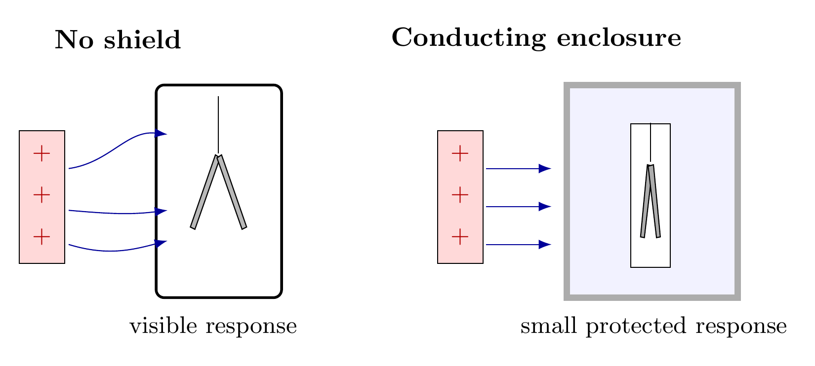
Figure 5. A closed conducting enclosure redistributes its surface charges so that external static
fields do not penetrate its empty cavity in ideal electrostatic equilibrium. Openings, insulation
gaps, and detector geometry matter in a real apparatus.
In an ideal closed conducting shell with no charge within the cavity, external electrostatic
disturbances do not produce an electric field inside the cavity at equilibrium. A shield need not be
connected to protective earth for this fundamental result; grounding may stabilize its potential and
reduce coupling through practical openings. Do not connect a homemade shield to a wall
outlet.
11 Experiment E: charge leakage and environmental effects
Question. Why does an electroscope gradually close even when no one touches it?
Procedure.
- Charge the electroscope until a reproducible opening is obtained.
- Leave all other objects stationary. Measure leaf separation s(t) every 10 to 30 s until it
approaches baseline.
- Repeat after cleaning and thoroughly drying the plastic support.
- Repeat at a different measured relative humidity if possible.
- Compare the decay curves and report the time at which the leaf separation crosses a
fixed threshold.
Physical model. An isolated conductor can be represented roughly by a capacitance Ceff to its
surroundings and a leakage resistance Rleak. Under the special assumption that both are constant
and there is no external charging,
The charge may follow an approximate exponential law while the leaf separation need not. The
calibration s(Q) is generally nonlinear and may include Friction and hysteresis. Therefore, fitting
s(t) to an exponential does not by itself measure the physical RC time constant. Treat the
threshold crossing as a comparative diagnostic.
12 From electroscope to electrometer
An electroscope indicates the presence of charge or electrostatic influence. An electrometer is an
instrument intended to measure an electrical quantity such as charge, potential, or an extremely
small current, with a specified calibration and uncertainty.
For an isolated conducting sensor, an elementary lumped approximation is
However, the effective capacitance depends on geometry, nearby hands, leads, the enclosure, and
the instrument input. The unknown capacitance prevents a leaf angle or a single uncalibrated
voltage reading from giving an absolute charge measurement.
A conventional DMM typically has a finite DC input resistance. In a simple measurement-loading
model, a sensor with capacitance Cs connected to a meter of resistance Rin relaxes
with
For illustration, Rin = 10 MΩ and Cs = 20 pF give
A charge signal would thus discharge very quickly through such an input. The meter would
strongly disturb the quantity being measured.
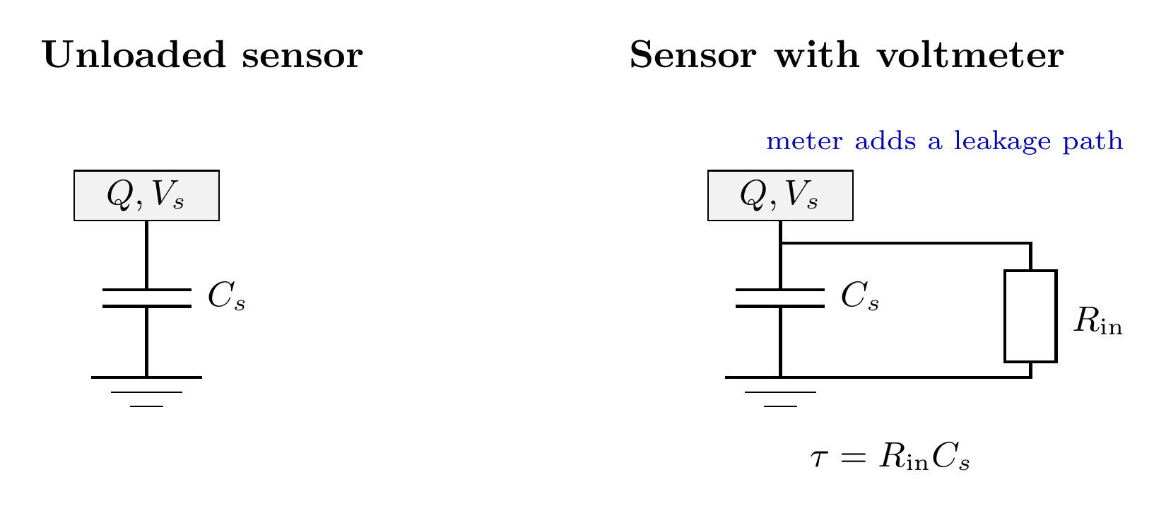
Figure 6. An isolated sensor has capacitance to its environment. Connecting a meter adds
conductance and capacitance, and a finite input resistance can rapidly discharge the sensor.
The electronic charge detector built in EDL02E1 provides a useful relative response through a
JFET and a current-sense resistor. It is not automatically a calibrated measurement of Q or E. A
more advanced instrument requires a guarded, very-high-impedance input or charge
amplifier together with calibration and leakage tests. The field and charge relationships in
EDL02E1 and the controlled charge-sharing procedure in EDL02E2 are complementary next
steps.
13 Making useful semiquantitative measurements
The simplest observable is the separation of the two foil tips. If the left and right tip coordinates in
a fixed image are xL and xR, define
For each rod position d, record s(d) and a baseline s0. The relative response
is reproducible if camera, leaf geometry, charging method, and surroundings are held
constant.
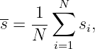
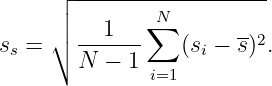
A more robust data set collects several charging trials and reports the average response and its
trial-to-trial scatter. If N readings are made for the same condition,
with sample standard deviation
The latter measures repeatability, not the total uncertainty. A systematic shift caused by a nearby
hand or a changed charge on the rod will not disappear by averaging.
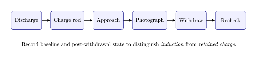
Figure 7. Experimental workflow: establish a baseline, apply one controlled electrostatic
perturbation, record the response, remove the perturbation, and check for a residual change.
14 Worked analysis examples
14.1 Example 1: What charge remains after induction?
A negatively charged plastic rod polarizes a neutral metal detector. The conductor is touched to
ground while the rod remains nearby. The ground contact is removed first, and then the rod is
withdrawn. What is the sign of the remaining charge?
Solution. During grounding, electrons are pushed away from the negative rod and leave the
detector. Removing the ground connection prevents them from returning. After the rod is removed,
the detector has a deficit of electrons and a positive net charge.
14.2 Example 2: Can an uncharged object attract a charged rod?
A negatively charged rod approaches an initially neutral metal sphere. The sphere moves toward
the rod. Does that prove the sphere was positively charged initially?
Solution. No. Electrons redistribute to the far side of the sphere, creating a positive region nearer
the negative rod. The nearer attraction can dominate the more distant repulsion even though the
total sphere charge was initially zero.
14.3 Example 3: A negative charge in an electric field
An electric field points to the right with magnitude 400 N∕C. An electron experiences what force
direction?
Solution. With F = qE and electron charge q = −1.602 × 10⁻¹⁹ C, the force is leftward, with
magnitude
The electric field does not reverse. Only the force direction reverses because q < 0.
14.4 Example 4: Why a voltmeter can erase the signal
An isolated sensor has Cs = 20 pF. It is connected to a 10 MΩ instrument input. Under the simple
lumped model, the signal drops to 1∕e of its initial potential in
A slow-handheld DMM display cannot follow this initial discharge, so it is not a suitable
unbuffered probe for this small isolated sensor.
15 Common misconceptions and troubleshooting
- The leaves opened, so charge must have been transferred. False. A nearby rod can
redistribute charge without changing the electroscope’s net charge.
- A neutral object cannot be attracted electrostatically. False. Polarization can produce
attraction.
- The leaves show the sign of charge. False. Leaf spreading alone normally responds to
either sign.
- Grounding creates charge. False. A ground connection permits charge to flow between
the detector and a reservoir.
- A Faraday shield works only if connected to Earth. False for an ideal closed conductor
shielding an empty cavity from external static fields.
- A larger opening means exactly twice the net charge. False without a validated
mechanical and electrostatic calibration.
- If a DMM gives zero volts, no static charge exists. False. The meter can discharge a
small isolated sensor during connection or measurement.
- The sign of a rubbed rod is fixed by its label. Not reliably. Material pairing, cleaning,
and humidity matter.
If no response is observed, check that the leaf wires are conductive, that the foil leaves
are light and free to move, and that the top terminal is electrically isolated from the
enclosure. If results change unpredictably, reduce drafts, handle the rod at a repeatable
location, clean insulating supports, and allow time for the detector to return to the
baseline.
16 Concept questions with answers
Question 1
A negatively charged rod approaches a neutral conductor without contact. Its near surface
becomes positive. Has net positive charge been created?
Answer. No. Electrons shifted to another part of the conductor. The conductor’s net charge
remains zero if it is isolated.
Question 2
Why must the grounding connection be removed before the charged rod in an induction
experiment?
Answer. Otherwise charge can flow between ground and detector while the external field
disappears. This tends to neutralize the charge that induction was meant to retain.
Question 3
Why can both a positively and negatively charged rod make an initially neutral electroscope
respond?
Answer. Both signs can redistribute existing charge. Reversal of the external field reverses the
induced charge pattern, but neither necessarily implies net charge transfer.
Question 4
A detector’s leaf separation decays steadily. Can one directly identify the leakage resistance from
its measured s(t) curve?
Answer. Not without an independent calibration linking s to sensor charge or potential,
and a model of the effective capacitance. The leaf mechanics may be nonlinear and
hysteretic.
Question 5
Why does an ordinary DMM present a problem for absolute charge measurements on a tiny
isolated sensor?
Answer. Its finite input resistance and capacitance load the sensor. The meter changes
the potential and can discharge the small amount of stored charge before a reading
stabilizes.
17 Laboratory notebook and completion criteria
A complete submission should include
- a photo or sketch of the apparatus with dimensions and leaf geometry;
- an equipment list and description of the charged materials;
- at least three response-versus-distance trials without contact;
- one persistent-contact charging trial and its discharge control;
- one ground-assisted induction trial and its reversed-order control;
- one shielding comparison at a matched rod position;
- a leaf-opening decay record with time and environmental conditions;
- plots or tables distinguishing measured data from predictions;
- a paragraph identifying the dominant systematic uncertainty;
- an explanation of why the experiment does not measure absolute charge or field
strength without further calibration.
The supplied blank CSV templates permit recorded data to be analyzed without modifying the
original readings. If an experiment produces no visible deflection, report that result and the
diagnosed limitation rather than fabricating a positive response.
18 Connection to the next experiments
EDL02 establishes field-driven charge redistribution and the difference between the charge of an
isolated conductor and an induced pattern of surface charges. EDL02E1 builds an electronic
detector with a measurable current response and a separate known-field electrode fixture.
EDL02E2 uses controlled charge sharing and separation ratios to test the inverse-square power of
Coulomb’s law. EDL03 will measure spatial variations of potential and reconstruct the electric field
from E = −∇V .
19 References and further reading
- OpenStax, University Physics, Volume 2, Chapter 5, “Electric Charges and Fields,”
especially Section 5.2, https://openstax.org/books/university-physics-volume-2/pages/5-2-conductors-insulators-and-charging-by-induction.
- College Board, AP Physics 2 Curriculum Module (2015), electroscope and electrophorus
laboratory construction notes, https://apcentral.collegeboard.org/media/pdf/ap-physics-2-curriculum-module-2015-ada.pdf.
- Princeton University, Physics 104 Laboratory, Experiment
I: “Build and Use an Electroscope to Explore Phenomena of Electrostatics” (2004),
https://kirkmcd.princeton.edu/examples/ph104_2004/ph104_exp01.pdf.
- D. J. Griffiths, Introduction to Electrodynamics, Chapters 2 and 3. This article is
independent and unofficial.
- PhysicsLibrary, EDL01: Practical Electricity and Measurement for Electrodynamics;
EDL02E1: Building an Electronic Electroscope; EDL02E2: Experimental Verification
of Coulomb’s Law by Charge Sharing.