Strapdown Inertial Navigation: What an Accelerometer Actually Measures
An accelerometer is often described casually as a device that “measures acceleration.” That
description is incomplete and, in inertial navigation, can be seriously misleading. An ideal
accelerometer does not directly measure the kinematic acceleration a of its case. It measures the
non-gravitational force per unit mass required to make an internal proof mass follow the motion of
the instrument.
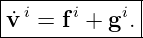
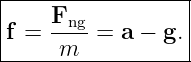
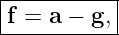
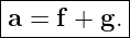
That quantity is called specific force. In an inertial frame,
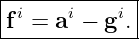
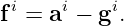
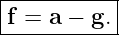
where g is gravitational acceleration. Equivalently,
This deceptively simple relationship is the translational heart of inertial navigation. The
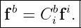
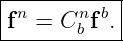
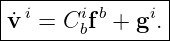
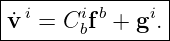
accelerometers supply f in the body frame. The navigation computer rotates that measurement
into a navigation frame, restores gravity, applies the rotating-frame corrections derived in INS02,
and integrates to obtain velocity and position [1, 2, 3].
The physics is easiest to understand by asking what happens to a small proof mass inside the
sensor. A supported accelerometer sitting motionless on a table reports a nonzero specific force
even though its coordinate acceleration is zero. The same accelerometer in ideal ballistic free fall
reports zero even though it is accelerating toward the Earth at nearly g. These are not paradoxes;
they are exactly what Newton’s second law predicts once gravitational and non-gravitational forces
are separated.
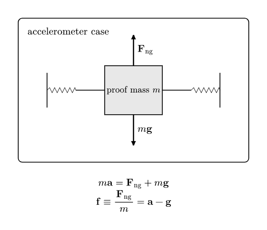
Figure. An ideal accelerometer contains a proof mass constrained to move with its case.
Gravity acts directly on the mass, while springs, electrostatic forces, or other
non-gravitational forces keep the proof mass centered. The accelerometer output is
proportional to this non-gravitational force per unit mass.
1 Learning objectives
After completing this entry, the reader should be able to:
- explain physically why an accelerometer does not directly measure coordinate
acceleration;
- derive the specific-force equation from Newton’s second law applied to an accelerometer
proof mass;
- distinguish gravitational force from the non-gravitational support force measured by
an accelerometer;
- explain why a stationary accelerometer reports approximately 1g;
- explain why an ideal freely falling accelerometer reports zero;
- calculate accelerometer outputs for elevators, vehicles, rockets, and other accelerating
systems;
- distinguish specific force from gravity and from apparent centrifugal terms;
- express specific force in body and navigation coordinates;
- show why a stationary level IMU in NED coordinates has fD ≈−g;
- explain how accelerometers provide roll and pitch information during static alignment;
- connect the accelerometer measurement to the inertial-frame velocity equation;
- identify which sensor imperfections are deliberately postponed to INS18.
2 The proof-mass model
Consider an accelerometer rigidly attached to a vehicle. Inside the accelerometer is a small proof
mass of mass m. In a MEMS accelerometer the proof mass is usually suspended by compliant
structures and its displacement is sensed capacitively. Closed-loop instruments may apply
electrostatic forces to keep the proof mass near a null position. The detailed implementation varies,
but the essential mechanics is the same [4, 1].
Let the proof mass have inertial acceleration a. Suppose the forces on it are separated into two
classes:
- gravitational force mg;
- all non-gravitational forces, whose vector sum is Fng.
Newton’s second law gives
Rearrange:
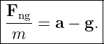
Divide by the proof-mass mass:
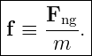
The left-hand side is the non-gravitational force per unit mass. Define
Therefore
This is the ideal accelerometer measurement equation in an inertial frame.
3 Why specific force has units of acceleration
Specific force is a force divided by mass, so its SI units are
That is why accelerometer outputs are naturally reported in acceleration units even though the
physical quantity is force per unit mass.
A common engineering unit is g0, the standard acceleration of gravity,
Thus an ideal stationary accelerometer near the Earth’s surface often has an output magnitude
close to 1g0.
4 Case 1: an accelerometer resting on a table
Choose a local Cartesian frame with +z upward. Near the Earth’s surface,
The accelerometer is stationary, so
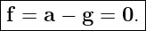
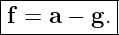
Specific force is therefore
| f | = a − g | (12)
|
| = 0 − (−gez) | (13)
|
| = gez . | (14) |
The accelerometer reports an upward specific force of approximately 1g.
Why? The proof mass would fall if unconstrained. The sensor structure must exert an upward
non-gravitational force on the proof mass to keep it motionless relative to the case. The
accelerometer senses that support interaction.
This is the same physics as a bathroom scale. A scale does not directly measure gravitational force;
it measures the contact force required to support the body.
5 Case 2: ideal free fall
Now release the accelerometer in vacuum and neglect all forces except gravity. Its inertial
acceleration is
Hence
The proof mass and sensor housing accelerate together under gravity. No support force is required
to keep the proof mass centered relative to the case, so the ideal accelerometer output is
zero.
This is the Newtonian expression of the physical idea behind weightlessness in orbit. An orbiting
spacecraft can have substantial coordinate acceleration toward the Earth while its occupants and
accelerometers experience nearly zero specific force.
6 Case 3: an accelerating elevator
Return to the local +z upward convention. Let the elevator have vertical acceleration
Then
| f | = a − g | (18)
|
| = (az + g)ez. | (19) |
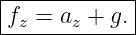
Thus
For g = 9.81 m∕s2:
| Motion | az (m∕s2) | ideal accelerometer output f
z (m∕s2) |
|
|
|
| stationary / constant velocity | 0 | 9.81 |
| accelerating upward | +2.00 | 11.81 |
| accelerating downward | −2.00 | 7.81 |
| ideal free fall | −9.81 | 0 |
The readings are also exactly what a passenger would describe as feeling heavier or
lighter.
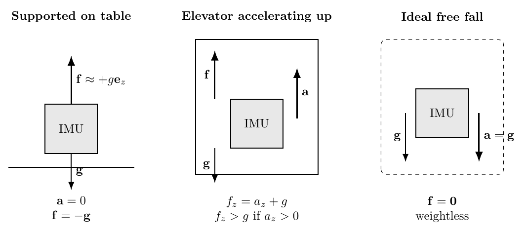
Figure. The same ideal accelerometer gives three very different outputs. On a table it
senses the upward support force; in an elevator accelerating upward it senses an even larger
support force; in ideal free fall it senses zero specific force even though its trajectory is
accelerating downward.
7 The accelerometer senses non-gravitational interactions
The definition
provides the most useful physical interpretation. Examples of non-gravitational forces
include:
- Normal force from a table or vehicle structure;
- thrust transmitted through a rocket or aircraft structure;
- aerodynamic forces;
- spring forces;
- contact forces from a tire, rail, or mechanical guide;
- electrostatic forces used to rebalance a precision accelerometer.
Gravity is intentionally excluded from Fng because the accelerometer cannot distinguish the
gravitational acceleration of the proof mass from the gravitational acceleration of the housing.
Both fall together.
Thus a useful conceptual statement is
8 A rocket example
Suppose a rocket is instantaneously vertical and accelerating upward at
Near the surface of the Earth,
Then
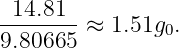
The ideal accelerometer therefore reports approximately
The rocket’s coordinate acceleration is only 5.0 m∕s2 upward, but its accelerometer senses a
larger specific force because thrust must both overcome gravity and produce the upward
acceleration.
9 Specific force is a vector
The scalar elevator examples are useful, but a strapdown INS operates with three-axis vectors. In
an inertial frame,
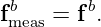
If the accelerometer triad is aligned with the body frame b, the IMU reports the body-resolved
components
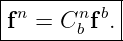
The navigation computer often needs the same physical specific-force vector expressed in the
navigation frame n:
INS01 showed that this is a passive coordinate transformation: the physical vector is unchanged;
only its components are re-expressed.
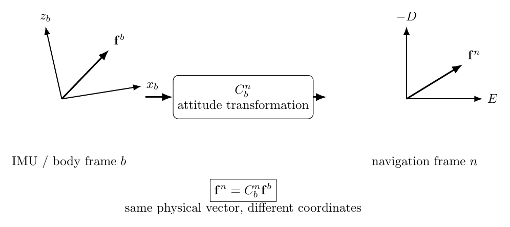
Figure. The accelerometer triad reports fb in body coordinates. The attitude solution
supplies Cbn, allowing the same physical vector to be resolved in the navigation frame as
fn = C
bnfb.
10 The basic inertial-frame navigation equation
Begin with the ideal inertial-frame specific-force equation
Since
we obtain
But the accelerometers provide body components fb. Transform them into the inertial
frame:
Therefore
This is the cleanest form of strapdown translational mechanization. It says:
- measure specific force in the body frame;
- use attitude to rotate it into the desired frame;
- restore gravity;
- integrate acceleration to obtain velocity.
Rotating Earth-fixed and local-level coordinates add the terms derived from the transport theorem
in INS02. Those terms do not change what the accelerometer measures; they change
the differential equation used to interpret that measurement in a rotating coordinate
frame.
11 Stationary IMU in local NED coordinates
The North-East-Down navigation convention deserves special attention because its signs are
initially counterintuitive.
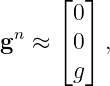
Let
because the D axis points downward.
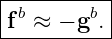
For a stationary IMU whose local coordinate acceleration is approximately zero,
Therefore
| fn | = an − gn | (37)
|
| ≈−gn | (38)
|
| =  . . | (39) |
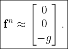
Thus a level stationary accelerometer in NED coordinates has approximately a negative Down
specific-force component. Physically, the support force points upward.
This sign is an excellent implementation sanity check.
12 Static leveling intuition
A stationary accelerometer triad measures approximately
Therefore the measured specific-force direction identifies local vertical. This is why accelerometers
can determine roll and pitch during coarse static alignment.
However, gravity alone provides no information about rotation around the vertical axis. If the body
is rotated in yaw while remaining level, the measured gravity direction in body coordinates is
unchanged. Yaw must come from another reference, such as Earth rate, a magnetic field, GNSS
velocity, or an external heading source.
That observability issue will be treated formally in INS09.
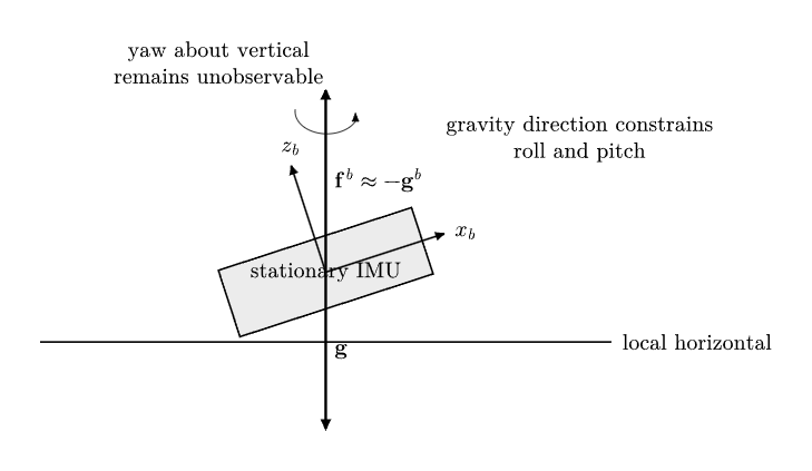
Figure. For a stationary IMU, the accelerometer vector points opposite the local gravity
vector. Its direction therefore constrains roll and pitch, but rotation about the vertical axis
remains unobservable from gravity alone.
13 Accelerometers and apparent weight
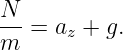
Suppose a person of mass m stands on a scale in an elevator. The scale measures the normal force
N. With +z upward,
Hence
But this is exactly the vertical specific force:
Thus an accelerometer and a scale are closely related physical instruments: both respond to
non-gravitational support force rather than to gravity directly.
This is why “apparent weight” is a useful intuition for specific force.
14 What about centrifugal acceleration?
INS02 showed that rotating coordinate frames introduce terms such as
It is important not to confuse these coordinate-kinematic terms with the accelerometer
measurement itself.
The proof mass responds to physical non-gravitational forces. The navigation equations may
combine gravitation and the Earth’s centrifugal contribution into a conventional local gravity
model. Different navigation texts therefore distinguish carefully among:
- gravitational acceleration or gravitation;
- centrifugal acceleration associated with Earth rotation;
- normal or effective gravity used by an Earth-fixed navigation model.
INS05 will derive these distinctions in detail. For the present article, the important principle is that
the definition of g must be consistent with the frame and mechanization equation in which it is
used [2, 3].
15 What the accelerometer cannot tell you by itself
An accelerometer measurement does not uniquely determine the vehicle’s coordinate acceleration
unless gravity and attitude are already known.
From
three ingredients are required:
- the measured body-frame specific force fb;
- the attitude transformation Cbn;
- the gravity model gn.
A tilt error therefore corrupts translational navigation even when the accelerometer itself is
perfect. If the estimated attitude tilts gravity by a small angle δ𝜃, the navigation computer can
interpret part of the large vertical support force as horizontal acceleration.
For a small tilt,
A one-degree attitude error gives approximately
That false horizontal acceleration is about 17 milli-g even with a perfect accelerometer. This
coupling is one reason attitude accuracy is so important in inertial navigation.
16 Ideal measurement versus a real IMU
The ideal relation is
A real three-axis accelerometer is better represented schematically by
where
- S represents scale-factor error;
- M represents axis nonorthogonality and cross-axis sensitivity;
- ba is accelerometer bias;
- na is measurement noise.
Temperature dependence, vibration rectification, saturation, quantization, and other effects may
also matter. These errors are deferred to INS18 so that the present article can isolate the
underlying physics.
17 The strapdown interpretation chain
The accelerometer is only the first step in the translational mechanization.
The ideal chain is
The important distinction is between the measured quantity and the reconstructed kinematic
quantity:
Instead,
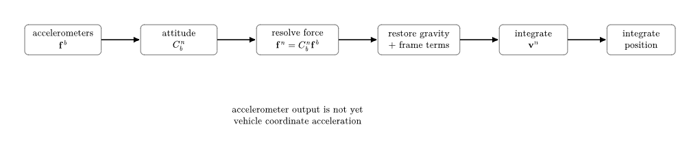
Figure. The accelerometer supplies body-resolved specific force, not navigation-frame
acceleration. Attitude, gravity, and the rotating-frame terms derived in INS02 are required
before velocity and position can be propagated.
18 Common misconceptions
18.1 “A stationary accelerometer should read zero”
A stationary accelerometer is not in free fall. Its support structure continuously applies a
non-gravitational force to its proof mass. Near the Earth’s surface, its ideal output magnitude is
approximately g.
18.2 “An accelerometer measures gravity”
An accelerometer does not directly measure gravitational acceleration. In ideal free fall its output
is zero even though gravitational acceleration is nonzero. Gravity is inferred through a model and
through the behavior of supported objects.
18.3 “Zero accelerometer output means zero acceleration”
No. Zero specific force means the accelerometer is following a locally ballistic trajectory. It may
have substantial coordinate acceleration.
18.4 “The navigation computer can integrate accelerometer data directly”
Not generally. The body-frame specific-force vector must first be transformed using attitude, and
gravity and rotating-frame terms must be handled consistently.
18.5 “The accelerometer gives yaw when the vehicle is stationary”
A static accelerometer provides the local vertical direction, which constrains roll and pitch. Gravity
is invariant under yaw rotations about the vertical, so yaw is not observable from accelerometers
alone.
19 Connection to the next lessons
INS03 has established the translational sensor equation
The next main lesson, INS04, asks the analogous rotational question:
INS05 will then return to the other half of the present equation and derive gravity models for a
rotating, oblate Earth. Once attitude, gyro measurements, specific force, and gravity are all
established, the series can assemble the complete strapdown mechanization without treating any
term as a black box.
20 Summary
For an ideal proof mass of mass m,
Therefore the accelerometer measures the non-gravitational force per unit mass,
A supported stationary accelerometer reads approximately 1g, while an ideal freely falling
accelerometer reads zero. The body-frame measurement must be rotated using the attitude
solution before it can contribute to navigation:
In an inertial frame,
For a stationary local-level system using NED coordinates,
Specific force is therefore the quantity that connects accelerometer physics to the translational
equations of strapdown inertial navigation.
References
[1] David H. Titterton and John L. Weston, Strapdown Inertial Navigation Technology,
2nd ed., Institution of Electrical Engineers, 2004.
[2] Paul D. Groves, Principles of GNSS, Inertial, and Multisensor Integrated Navigation
Systems, 2nd ed., Artech House, 2013.
[3] Christopher Jekeli, Inertial Navigation Systems with Geodetic Applications, Walter
de Gruyter, 2001.
[4] Anthony Lawrence, Modern Inertial Technology: Navigation, Guidance, and Control,
2nd ed., Springer, 1998.
[5] Paul G. Savage, Strapdown Analytics, Strapdown Associates, 2000.



![-N- kg-m-∕s2 2
[f] = kg = kg = m ∕s .](https://images.physicslibrary.org/cache/objects/1348/make4ht/StrapdownInertialNavigationWhatAnAccelerometerActuallyMeasures7x.png)