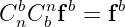
Strapdown Inertial Navigation Examples: Specific Force and Accelerometer Physics
This companion to INS03 turns the specific-force equation into a working calculation tool. The
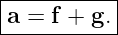
central relationship is
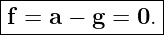
or equivalently
The exercises deliberately mix ordinary mechanics, coordinate transformations, static leveling, and
navigation implementation checks. The purpose is to make the reader comfortable answering two
different questions:
- What will an ideal accelerometer report in a given physical situation?
- Given an accelerometer measurement, what additional information is required to
reconstruct vehicle acceleration?
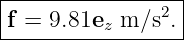
Unless otherwise stated, use
When standard-gravity units are requested, use
The notation follows INS03 and standard inertial-navigation references [1, 2, 3, 4]. Body axes use
the aerospace forward-right-down convention when explicitly stated, and the local navigation frame
is North-East-Down (NED).
1 Exercises
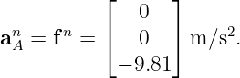
Exercise 1: A supported proof mass on a table
A small ideal accelerometer has a proof mass
It rests motionless on a horizontal table. Use a local Cartesian frame with +z upward.
- Write the gravitational acceleration vector g.
- Find the inertial acceleration a of the accelerometer.
- Find the specific force f.
- Find the total non-gravitational force acting on the proof mass.
- Express the accelerometer output magnitude in units of g0.
- Explain why the answer is nonzero although the accelerometer is motionless.
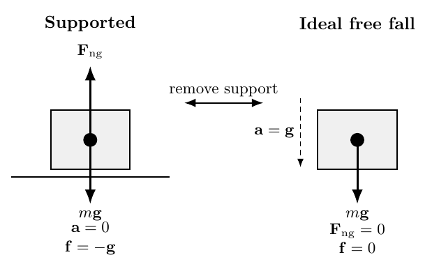
Figure. A supported proof mass requires a non-gravitational force to avoid free fall. In
ballistic free fall the support interaction disappears and the ideal accelerometer output goes
to zero.
Exercise 2: Elevator readings and apparent weight
A 75.0 kg passenger stands on a scale in an elevator. An ideal accelerometer is rigidly attached to
the elevator. Again take +z upward.
For each of the following cases, find the accelerometer output fz and the scale Normal force
N:
- constant velocity;
- upward acceleration az = +2.50 m∕s2;
- downward acceleration az = −3.00 m∕s2;
- ideal cable-break free fall.
Explain why the accelerometer and the scale tell essentially the same mechanical story.
Exercise 3: Engine cutoff during an upward flight
A vehicle is moving vertically upward at 500 m∕s near the Earth’s surface. At one instant its
engine is shut off and aerodynamic drag is neglected.
- Immediately after engine cutoff, what is its coordinate acceleration?
- What does its ideal accelerometer read?
- Does the fact that the vehicle is moving upward at 500 m∕s change the accelerometer
result?
- Later, suppose the engine produces a net vehicle acceleration of +15.0 m∕s2 upward.
What specific force must then be measured?
Use the result to explain why zero accelerometer output does not mean zero coordinate
acceleration.
Exercise 4: Level car accelerating horizontally
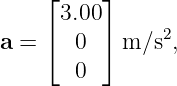
A CAR travels on a level road and accelerates eastward at
Use a local frame with +x east and +z upward.
- Write a and g.
- Compute the specific-force vector f.
- Find |f|.
- Find the angle of f from the upward vertical.
- Identify the physical non-gravitational interactions producing the horizontal and
vertical components.
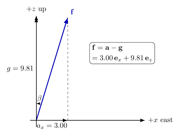
Figure. A level car accelerating horizontally has both an upward support component and
a horizontal traction component in its specific-force vector.
Exercise 5: Body-frame accelerometer data to NED acceleration
A level vehicle uses forward-right-down body axes. Its heading is
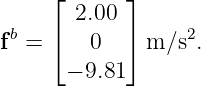
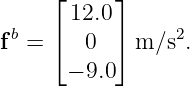
measured east of north. Its ideal accelerometers report
Assume the vehicle is level and neglect Earth rotation for this exercise.
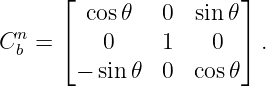
- Construct the body-to-NED DCM Cbn.
- Compute fn = C
bnfb.
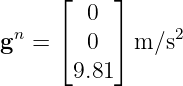
- Add the NED gravity vector
to recover an.
- Interpret the north, east, and down components of the result.
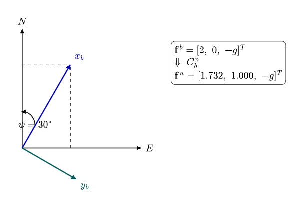
Figure. A forward body-axis specific force must be resolved into North and East before
gravity is restored and the navigation acceleration is formed.
Exercise 6: Static leveling from accelerometer components
A stationary IMU uses forward-right-down body axes. Its true roll and pitch are
Yaw is arbitrary. Assume the local navigation frame is NED and
For the usual yaw-pitch-roll attitude convention, show that a static accelerometer satisfies
Then:
- compute fx,fy,fz numerically;
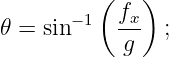
- recover pitch from
- recover roll from
- explain why yaw cannot be obtained from the accelerometer vector alone.
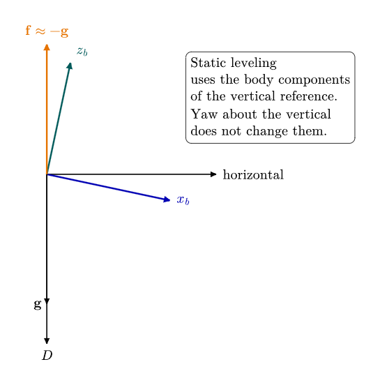
Figure. During static alignment the accelerometer observes the direction opposite gravity.
Roll and pitch change the body components of that vector; yaw about the local vertical
does not.
Exercise 7: Small attitude error produces false horizontal acceleration
A vehicle is actually stationary and level. Its accelerometers are perfect, but the navigation
computer’s attitude estimate has a constant pitch error of
Assume the only consequence is that the vertical specific-force vector is rotated incorrectly into the
navigation frame.
- Find the exact magnitude of the false horizontal acceleration using g sin δ𝜃.
- Compare it with the small-angle approximation gδ𝜃 when δ𝜃 is in radians.
- If this false acceleration remains constant for 60 s, estimate the resulting horizontal
velocity error.
- Estimate the horizontal position error after 60 s.
- Explain why attitude accuracy is inseparable from accelerometer accuracy in a
strapdown INS.
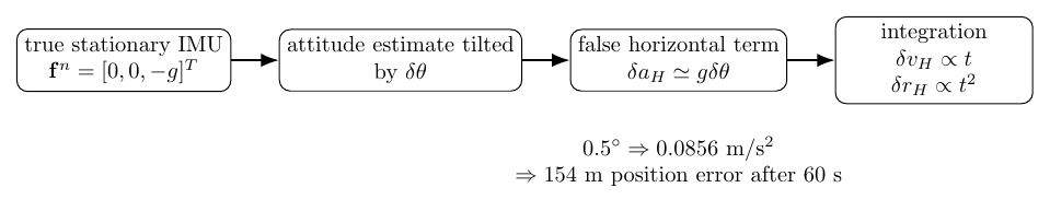
Figure. A small tilt error projects part of the large vertical specific-force vector into a
horizontal navigation channel. The resulting false acceleration is then integrated into
velocity and position error.
Exercise 8: Accelerometer on a horizontal rotating arm
An accelerometer is mounted at radius
on a horizontal arm rotating at constant angular speed
At the instant of interest define +x radially outward and +z upward. Neglect Earth rotation but
retain gravity.
- Find the coordinate acceleration a.
- Compute the specific force f = a − g.
- Find its magnitude in m∕s2 and in units of g
0.
- Find the angle of the measured specific-force vector away from the upward vertical
toward the rotation axis.
- Explain which physical forces produce the two measured components.
Exercise 9: A pitched vehicle – complete specific-force reconstruction
A vehicle uses forward-right-down body axes and NED navigation coordinates. At one instant it
has zero roll and yaw and a nose-up pitch angle
The body-frame accelerometer vector is
Use
Neglect Earth rotation.
- Compute fn.
- Add gn = [0 0 9.81]T m∕s2.
- Find the north and vertical coordinate accelerations.
- State whether the vehicle is accelerating upward or downward.
Exercise 10: Navigation-code sanity checks
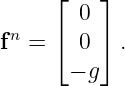
A stationary, level IMU in NED coordinates ideally has
A programmer makes two different mistakes.
- Code A treats fn directly as coordinate acceleration. What down-velocity and
vertical-position error does it accumulate after 30 s from rest?
- Code B computes an = fn − gn instead of adding gravity. What down-velocity and
vertical-position error does it accumulate after 30 s?
- State the correct stationary result.
- Propose at least four unit tests that should be placed around a strapdown specific-force
implementation.
2 Worked solutions
Solution 1: A supported proof mass on a table
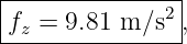
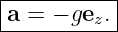
With +z upward,
The accelerometer is stationary, so
Specific force is
| f | = a − g | (23)
|
| = 0 − (−9.81ez), | (24) |
hence
The proof mass is
Because f = Fng∕m,
| Fng | = mf | (27)
|
| = (0.0200)(9.81)ez, | (28) |
so
In units of standard gravity,
The reading is nonzero because the proof mass is not allowed to follow its natural gravitational
free-fall trajectory. The sensor structure supplies an upward non-gravitational force
that keeps the mass fixed relative to the case. The accelerometer senses that support
interaction.
Solution 2: Elevator readings and apparent weight
For vertical motion with +z upward,
The passenger’s scale normal force satisfies
so
Thus the accelerometer’s specific force and the passenger’s scale force per unit mass are the same
mechanical quantity in this idealized one-dimensional problem.
For constant velocity,
so
and
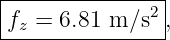
For upward acceleration az = +2.50 m∕s2,
and
For downward acceleration az = −3.00 m∕s2,
and
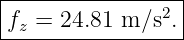
In ideal cable-break free fall,
so
This is why a falling elevator occupant feels weightless: both the person and the elevator are
following nearly the same gravitational trajectory, so the support interaction vanishes.
Solution 3: Engine cutoff during an upward flight
Immediately after engine cutoff, gravity remains. Neglecting drag,
Because
specific force is
The upward velocity of 500 m∕s does not appear in the ideal specific-force relation. Velocity affects
the trajectory, but with the stated assumptions it does not create a non-gravitational force. At
the instant after shutdown, the vehicle is ballistic and its ideal accelerometer reads
zero.
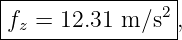
When the engine later produces a net coordinate acceleration of +15.0 m∕s2 upward,
| fz | = az − (−g) | (46)
|
| = 15.0 + 9.81, | (47) |
so
This example separates velocity, coordinate acceleration, and accelerometer output. They are three
different quantities.
Solution 4: Level car accelerating horizontally
The coordinate acceleration is
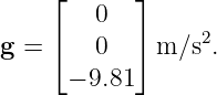
while gravity is
Therefore
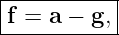
| f | = a − g | (51)
|
| =  m∕s2. m∕s2. | (52) |
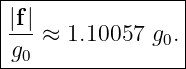
Thus
Its magnitude is
| |f| | =  | (54)
|
| ≈ 10.2585 m∕s2 . | (55) |
The angle away from the upward vertical is
The vertical component comes from the road supporting the vehicle against gravity. The horizontal
component comes from tire-road traction transmitted through the vehicle structure.
Both are non-gravitational interactions and therefore both appear in the accelerometer
measurement.
Solution 5: Body-frame accelerometer data to NED acceleration
For a level vehicle with heading ψ, the body x axis points in the horizontal direction
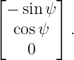
when resolved in NED coordinates. The right body axis resolves as
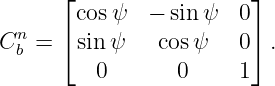
Therefore
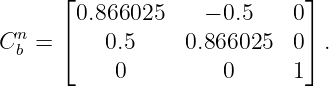
At ψ = 30∘,
Transform the accelerometer vector:
| fn | = C
bnfb | (61)
|
| = 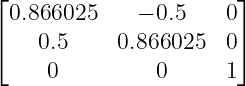  . . | (62) |
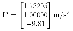
Hence
Now restore gravity:
| an | = fn + gn | (64)
|
| =  m∕s2. m∕s2. | (65) |
Therefore
The horizontal acceleration magnitude is 2.00 m∕s2, exactly equal to the forward specific-force
component, and it points 30∘ east of north. The −9.81 m∕s2 down component of specific force
cancels the +9.81 m∕s2 gravity vector because the vehicle is level and has no vertical
acceleration.
This is the basic strapdown sequence:
Solution 6: Static leveling from accelerometer components
For the usual yaw-pitch-roll convention, the body-to-NED DCM has third row
Because
and
the body components are minus g times the third row of Cbn:
With
we obtain
| fx | = 9.81 sin(−5∘) | (75)
|
| ≈−0.8550 m∕s2 , | (76) |
| fy | = −9.81 sin(10∘) cos(−5∘) | (77)
|
| ≈−1.6970 m∕s2 , | (78) |
and
| fz | = −9.81 cos(10∘) cos(−5∘) | (79)
|
| ≈−9.6242 m∕s2 . | (80) |
The magnitude remains
as expected for an ideal stationary accelerometer in the assumed uniform field.
Recover pitch:
| 𝜃 | = sin −1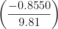 | (82)
|
| ≈−5.00∘ . | (83) |
Recover roll:
| ϕ | = atan2(−fy,−fz) | (84)
|
| = atan2(1.6970, 9.6242) | (85)
|
| ≈ 10.00∘ . | (86) |
Yaw is not observable because rotating the vehicle about the local vertical does not change the
direction of gravity relative to that vertical. The accelerometer provides a vertical reference, not a
north reference.
Solution 7: Small attitude error produces false horizontal acceleration
Convert the attitude error to radians:
The exact horizontal projection of the vertical specific-force vector is
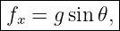
| δaH | = g sin δ𝜃 | (88)
|
| = 9.81 sin(0.50∘) | (89)
|
| ≈ 0.0856073 m∕s2 . | (90) |
The small-angle approximation gives
| gδ𝜃 | = (9.81)(0.00872665) | (91)
|
| ≈ 0.0856084 m∕s2 . | (92) |
The difference is only about 1.1 × 10⁻⁶ m∕s2 here, so the linear approximation is excellent.
If the false acceleration is constant for t = 60 s,
The corresponding position error from rest is
| δrH | =  δaHt2 δaHt2 | (94)
|
| ≈ (0.0856073)(60)2 (0.0856073)(60)2 | (95)
|
| ≈ 154.1 m . | (96) |
This result is fundamental to strapdown navigation. The accelerometer itself can be perfect, but if
attitude is wrong, the navigation computer resolves the large vertical support vector into the
wrong directions. Attitude errors therefore become acceleration errors before the first velocity
integration even occurs.
Solution 8: Accelerometer on a horizontal rotating arm
The centripetal coordinate acceleration is directed inward. Since +x is radially outward,
Numerically,
so
Gravity is
Therefore
| f | = a − g | (101)
|
| = −4.50ex + 9.81ez. | (102) |
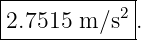
Thus
Its magnitude is
| |f| | =  | (104)
|
| ≈ 10.7929 m∕s2 . | (105) |
In standard-gravity units,
The angle from the upward vertical toward the rotation axis is
The upward component is generated by the structural support against gravity. The
inward component is generated by the arm supplying the centripetal force needed to
keep the accelerometer on its circular path. Both are non-gravitational, so both are
sensed.
Solution 9: A pitched vehicle – complete specific-force reconstruction
With 𝜃 = 20∘,
Therefore
| fn | = C
bnfb | (109)
|
| = 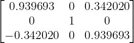  . . | (110) |
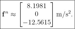
The north component is
| fN | = (0.939693)(12.0) + (0.342020)(−9.0) | (111)
|
| ≈ 8.1981 m∕s2 . | (112) |
The east component is zero. The down component is
| fD | = (−0.342020)(12.0) + (0.939693)(−9.0) | (113)
|
| ≈−12.5615 m∕s2 . | (114) |
Hence
Restore gravity:
| an | = fn + gn | (116)
|
| = 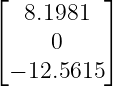 + +  | (117)
|
| = 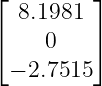 m∕s2. m∕s2. | (118) |
Therefore
and
Because NED takes positive D downward, negative down acceleration means the vehicle is
accelerating upward at approximately
This example shows why one must transform the full specific-force vector before adding gravity.
Gravity cannot simply be added to the body z channel unless body and navigation vertical axes
are actually aligned.
Solution 10: Navigation-code sanity checks
The correct stationary relation is
Code A incorrectly uses
Starting from rest, after 30 s,
The down-position error is
| ΔDA | =  (−9.81)(30)2 (−9.81)(30)2 | (125)
|
| = −4414.5 m . | (126) |
A negative down displacement corresponds to an erroneous altitude increase of 4414.5
m.
Code B computes
| aBn | = fn − gn | (127)
|
| =  m∕s2. m∕s2. | (128) |
Thus
and
| ΔDB | =  (−19.62)(30)2 (−19.62)(30)2 | (130)
|
| = −8829 m . | (131) |
The correct stationary result is
apart from whatever Earth-rotation and gravity-model details are included in the chosen full
mechanization.
Useful unit tests include:
- Stationary level NED test:
must produce zero translational acceleration.
- Ideal free-fall test: f = 0 must reconstruct a = g in an inertial-frame calculation.
- Horizontal acceleration test: a level vehicle with fN = 2 m∕s2 and f
D = −g must
reconstruct aN = 2 m∕s2 and a
D = 0.
- Attitude transformation test: rotate a known body specific-force vector by a
known DCM and compare the result with a hand-computed navigation-frame
vector.
- Gravity sign test: in NED, gravity is positive down while the static accelerometer specific
force is negative down.
- norm preservation test: a pure rotation must satisfy
- Round-trip frame test:
to numerical precision.
These are inexpensive tests and catch several of the most destructive sign, frame, and
interpretation errors before they enter the velocity and position integrations.
3 What these exercises establish
The worked examples reinforce the physical and computational ideas that will recur throughout
the strapdown series:
- An accelerometer measures non-gravitational force per unit mass, not coordinate
acceleration directly.
- A supported stationary accelerometer reads approximately 1g, whereas an ideal freely
falling accelerometer reads zero.
- Velocity by itself does not determine accelerometer output.
- Horizontal traction and vertical support forces combine vectorially in the accelerometer
measurement.
- Body-frame accelerometer data must be transformed by attitude before gravity can be
restored in the navigation frame.
- Static gravity provides roll and pitch information but not yaw.
- A small attitude error can project gravity-scale specific force into a horizontal channel
and create rapidly growing navigation error.
- Circular motion produces a horizontal specific-force component. A non-gravitational
centripetal force is required to hold the sensor on the circular path.
- Gravity must be added using the correct frame and sign convention. Treating specific
force as coordinate acceleration produces enormous integrated errors.
These results prepare the reader for INS04, which asks the rotational analogue of INS03: what does
a gyroscope actually measure?
References
[1] D. H. Titterton and J. L. Weston, Strapdown Inertial Navigation Technology, 2nd
ed., IET, 2004.
[2] P. D. Groves, Principles of GNSS, Inertial, and Multisensor Integrated Navigation
Systems, 2nd ed., Artech House, 2013.
[3] C. Jekeli, Inertial Navigation Systems with Geodetic Applications, Walter de Gruyter,
2001.
[4] A. Lawrence, Modern Inertial Technology: Navigation, Guidance, and Control, 2nd
ed., Springer, 1998.
[5] P. G. Savage, Strapdown Analytics, Strapdown Associates, 2000.




































![[− sin 𝜃 sin ϕ cos𝜃 cosϕ cos 𝜃].](https://images.physicslibrary.org/cache/objects/1349/make4ht/StrapdownInertialNavigationExamplesSpecificForceAndAccelerometerPhysics61x.png)





















![fn = [0 0 − g]T, gn = [0 0 g]T](https://images.physicslibrary.org/cache/objects/1349/make4ht/StrapdownInertialNavigationExamplesSpecificForceAndAccelerometerPhysics100x.png)