Waves on Strings: Reflection, Transmission, and Mechanical Impedance
M06-08 developed traveling and Standing Waves on a uniform stretched string.
A new phenomenon appears when a traveling wave encounters a change in the string.
At an interface, the incoming wave generally separates into:
- a reflected wave traveling back into the first string,
- a transmitted wave traveling into the second string.
The amount reflected and transmitted is controlled by the mechanical impedance of the two
strings.
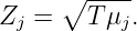
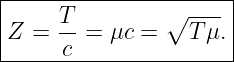
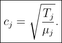
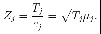
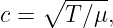
For an ideal transverse string,
where
For a lossless junction between strings with impedances
and
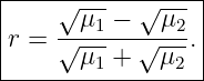
the displacement-amplitude coefficients are
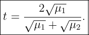
and
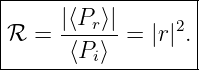
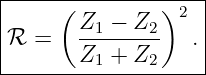
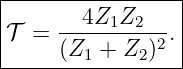
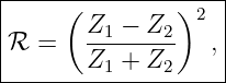
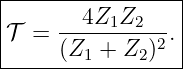
The corresponding Power fractions are
and
For lossless strings,
These relations unify ordinary string reflection, fixed and free boundaries, impedance matching,
and the formation of standing waves.
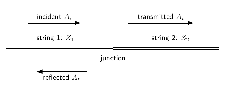
Figure 1. A right-moving incident wave reaches a junction between two strings. In general, part of
the wave is reflected into string 1 and part is transmitted into string 2.
1 Two joined strings
Let the interface be at
String 1 occupies
and has parameters
String 2 occupies
and has
Their wave speeds are
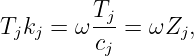
Their characteristic mechanical impedances are
For the common textbook case of two segments of one stretched string, the static tension is the
same on both sides:
2 Incident, reflected, and transmitted waves
Use complex notation and take the physical displacement to be the real part.
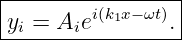
The incident wave is
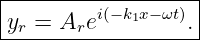
The reflected wave is
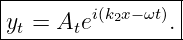
The transmitted wave is
All three waves have the same angular frequency
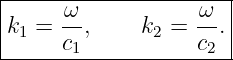
The wave numbers are
The wavelength can change across the junction even though the frequency does not.
3 First boundary condition: displacement continuity
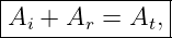
If the two strings remain attached at the junction, the junction has one transverse displacement.
Therefore
At
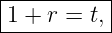
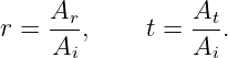
Thus
where
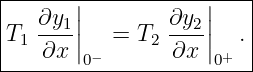
4 Second boundary condition: transverse force continuity
For small slope, the transverse component of tension is proportional to
At a massless junction with no external transverse force, the transverse force must be
continuous:
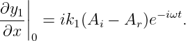
On string 1,
Therefore
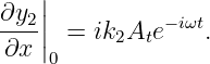
On string 2,
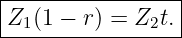
Hence
Since
Equivalently,
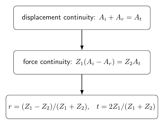
Figure 2. An ideal massless junction imposes two conditions: the string displacement is continuous
and the transverse tension force is continuous. These two conditions determine the reflected and
transmitted amplitudes.
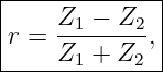
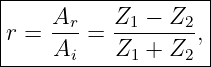
5 Displacement reflection coefficient
Use
Then
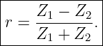
Therefore
Thus
This coefficient includes the phase of the reflected displacement.
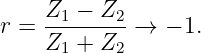
For positive real impedances:
- Z2 > Z1 gives r < 0,
- Z2 < Z1 gives r > 0,
- Z2 = Z1 gives r = 0.
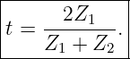
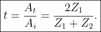
6 Displacement transmission coefficient
Since
| t | = 1 +  | (41)
|
| =  . . | (42) |
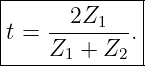
Therefore
The displacement transmission amplitude can exceed unity.
That does not imply that transmitted power exceeds incident power, because the power also
depends on the impedance.
7 Mechanical impedance of a traveling string wave
Consider a right-moving sinusoidal wave
The transverse velocity is
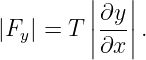
The transverse force magnitude associated with the local slope is
For the sinusoid,
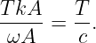
Thus the force-to-velocity amplitude ratio is
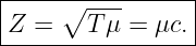
Therefore
Using
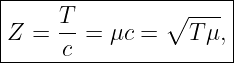
Its SI units are
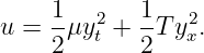
8 Instantaneous power carried by a string wave
The local mechanical energy density is
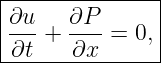
Using the wave equation, one obtains the energy continuity relation
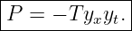
where the instantaneous power flow in the positive
direction is
This sign convention makes
for a right-moving traveling wave.
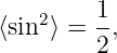
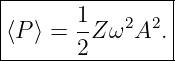
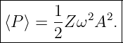
9 Average power of a sinusoidal wave
For
and
Therefore
Since
Using
For a left-moving wave, the power flux has the opposite sign.
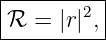
10 Power reflection coefficient
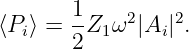
The incident average power magnitude is
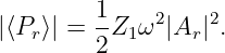
The reflected wave carries power in the negative
direction with magnitude
Therefore the reflected power fraction is
For real positive string impedances,
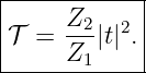
11 Power transmission coefficient
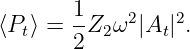
The transmitted average power is
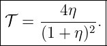
Therefore
| 𝒯 | =  | (72)
|
| =  |t|2. |t|2. | (73) |
Hence
12 Energy conservation at the junction
For a lossless ideal junction,
| ℛ + 𝒯 | = 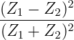 + + 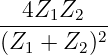 | (75)
|
| = 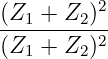 | (76)
|
| = 1. | (77) |
Therefore
Amplitude conservation is not the correct energy statement.
Power conservation is.
13 Same tension but different linear densities
Suppose the two strings have the same tension:
Then
The reflection coefficient becomes
The transmission coefficient is
Since
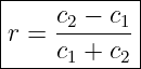
the reflection coefficient can also be written
for equal tension.
14 Phase reversal
If the wave travels from lower impedance to higher impedance,
then
The reflected displacement is inverted.
This is a phase change of
If the wave travels from higher impedance to lower impedance,
then
The reflected displacement is not inverted.
The sign of
therefore contains direct physical information.
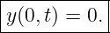
15 Fixed-end reflection
A perfectly fixed end requires
Thus at the end,
Therefore
The reflected displacement has the same magnitude as the incident wave but is inverted.
No average power passes through the fixed boundary:
The fixed end is a displacement node.
16 Free-end reflection
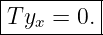
At a free end, the transverse force vanishes:
For nonzero
This requires
Therefore
The reflected displacement is not inverted.
The free end is a displacement antinode.
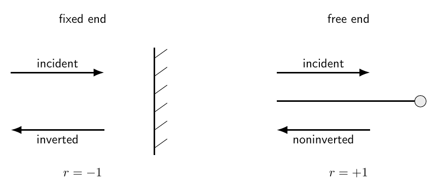
Figure 3. A fixed end reflects displacement with a sign reversal, while a free end reflects without
inversion. Both ideal boundaries reflect all incident power.
17 Fixed and free ends as impedance limits
The junction formula gives an intuitive impedance interpretation.
For
This is the fixed-end limit.
For
This is the free-end limit.
Thus fixed and free boundaries are the extreme high- and low-impedance limits of the same
reflection physics.
18 Impedance ratio
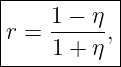
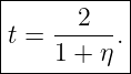
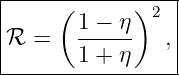
Define
Then
and
These forms make the dependence on impedance mismatch especially clear.

Figure 4. Displacement reflection and transmission amplitudes versus impedance ratio η = Z2∕Z1.
The reflected displacement changes sign when the second string has the larger impedance.
19 Power coefficients versus impedance ratio
In terms of
and
Both are nonnegative.
At
For very large or very small impedance ratio,

Figure 5. Reflected and transmitted power fractions for a lossless junction. Transmission is
complete when the impedances match, while extreme mismatch approaches total reflection.
20 Impedance matching
If
then
and
Therefore
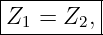
The interface becomes reflectionless in this ideal model.
Matching the wave speed is not the fundamental criterion.
Matching the mechanical impedance is.
For two strings with different tensions and densities, it is possible to have
while still having
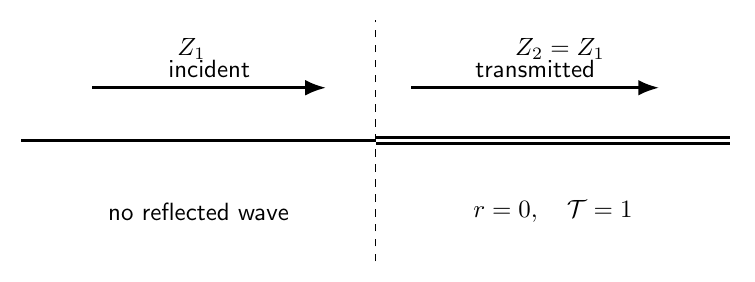
Figure 7. When the string impedances are equal, the interface produces no reflected wave. The
transmitted wavelength may still differ if the two wave speeds differ.
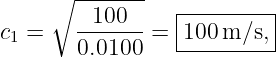
21 Example 1: wave from a light string into a heavy string
Let the common tension be
Take
and
Then
while
The impedances are
and
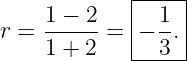
Therefore
The reflected displacement is inverted.
The transmitted amplitude coefficient is
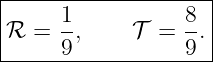
The power coefficients are
and
Most of the power is transmitted even though the transmitted displacement amplitude is
smaller.
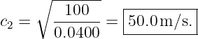
22 Example 2: wave from heavy string into light string
Reverse the direction of incidence.
Now
Then
The reflected displacement is not inverted.
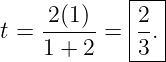
The transmitted displacement coefficient is
The transmitted displacement amplitude exceeds the incident amplitude.
Nevertheless,
The power fractions are unchanged when the direction is reversed for this lossless two-string
junction.
23 Why t > 1 does not violate energy conservation
In Example 2,
If amplitude alone measured power, that result would look impossible.
But
The transmitted string has the smaller impedance.
Therefore a larger displacement amplitude can carry less power per unit amplitude
squared.
The correct energy test is always
24 Pulse interpretation
The sinusoidal coefficients also describe sufficiently narrowband pulses locally.
A pulse moving from low impedance toward high impedance produces:
- an inverted reflected pulse,
- a transmitted pulse with reduced displacement amplitude.
A pulse moving from high impedance toward low impedance produces:
- a noninverted reflected pulse,
- a transmitted pulse that can have a larger displacement amplitude.
The pulse shapes remain idealized only when the media are nondispersive and the interface itself
has no frequency-dependent dynamics.
25 Standing waves from reflection
Suppose a right-moving incident wave and its reflected wave occupy the same uniform
string:
If
the two waves have equal amplitude.
Their interference produces a pure standing wave.
For a fixed end,
The end is a node.
For a free end,
The end is an antinode.
Thus boundary reflection phase directly determines the standing-wave geometry.
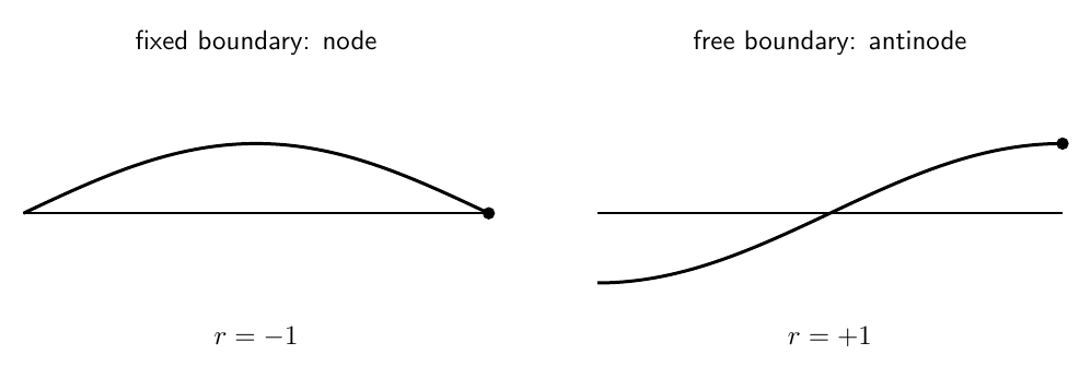
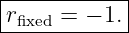
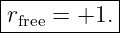
Figure 6. Reflection phase determines whether the boundary is a displacement node or antinode.
A fixed end has r = −1, while a free end has r = +1.
26 Normal-mode conditions from round-trip phase
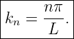
Reflection provides another derivation of the normal-mode spectra from M06-08.
A wave traveling across a string of length
and back accumulates propagation phase
It also acquires reflection phases at the two ends.
A self-consistent normal mode requires the total round-trip phase to be an integer multiple
of
27 Fixed-fixed resonance condition
Each fixed reflection contributes phase
Two fixed reflections contribute
which is equivalent to zero phase modulo
Therefore
Hence
This reproduces the fixed-fixed normal-mode result.
28 Fixed-free resonance condition
A fixed reflection contributes
while a free reflection contributes zero displacement phase shift.
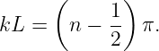
Therefore
Hence
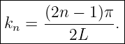
Equivalently,
This reproduces the fixed-free spectrum.
29 Partial reflection and imperfect standing waves
If
the counter-propagating waves do not have equal amplitudes.
The resulting pattern contains both:
- spatial interference,
- net energy transport.
It is not a pure standing wave.
Nodes no longer remain exact zero-displacement points unless special additional conditions
apply.
This distinction becomes important in resonators with lossy or partially transmitting
boundaries.
30 Multiple reflections
If a wave enters a finite segment bounded by two impedance changes, it can reflect
repeatedly.
Each round trip produces:
- propagation phase,
- reflection amplitudes,
- reflection phase shifts.
The outgoing wave is then a superposition of many delayed contributions.
This mechanism underlies:
- echoes,
- resonant buildup,
- interference fringes,
- frequency-selective transmission.
A later wave-analysis article can treat these effects using complex amplitudes and geometric
series.
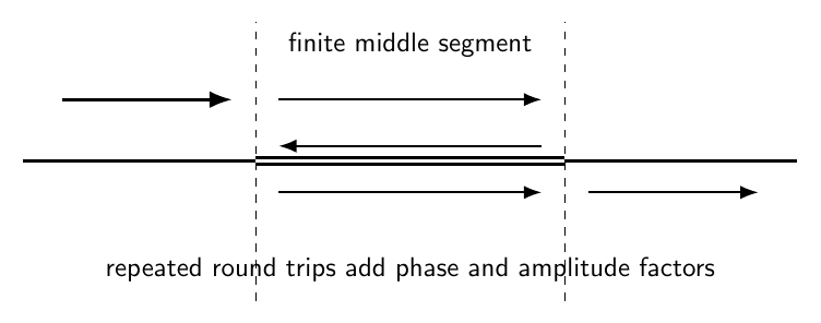
Figure 8. A finite string segment between two mismatched interfaces produces repeated internal
reflections. Successive transmitted contributions can interfere constructively or destructively.
31 Connection to other wave systems
The impedance principle is much broader than strings.
Analogous ideas occur in:
The detailed definition of impedance changes from system to system, but the general principle
remains:
Reflection is controlled by mismatch between the wave impedances presented on
the two sides of a boundary.
32 Common mistakes
- Confusing wave speed with mechanical impedance.
- Writing Z = Tc instead of Z = T∕c.
- Forgetting that Z =
 for the ideal string.
- Applying displacement continuity but forgetting transverse-force continuity.
- Using Ai − Ar = At for displacement continuity instead of Ai + Ar = At.
- Losing the minus sign in the reflected-wave spatial derivative.
- Confusing displacement amplitude coefficients with power coefficients.
- Assuming 𝒯 = |t|2 when the two impedances differ.
- Interpreting t > 1 as a violation of energy conservation.
- Forgetting that low-to-high impedance reflection is inverted.
- Forgetting that high-to-low impedance reflection is noninverted.
- Reversing the fixed-end and free-end reflection signs.
- Calling a partially reflected pattern a pure standing wave.
- Assuming equal wave speeds are required for impedance matching.
- Forgetting that the frequency remains the same across a stationary linear interface
while wavelength can change.
33 Practice exercises
- Derive the mechanical impedance Z = T∕c =
 of an ideal string.
- Derive the displacement and transverse-force boundary conditions at a massless
junction.
- Starting from those two conditions, derive r and t.
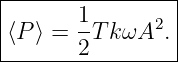
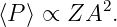
- Derive the average power ⟨P⟩ =
 Zω2A2 of a sinusoidal traveling wave.
- Derive the power coefficients ℛ and 𝒯 .
- Verify algebraically that ℛ + 𝒯 = 1.
- For equal tension, express r in terms of μ1 and μ2.
- For equal tension, express r in terms of c1 and c2.
- Derive the fixed-end and free-end reflection coefficients directly from their boundary
conditions.
- Recover the fixed and free limits from Z2 →∞ and Z2 → 0.
- Reproduce both numerical examples in this article.
- Show explicitly why reversing the direction of incidence changes the sign of r but leaves
ℛ unchanged.
- Derive the fixed-fixed normal-mode condition using round-trip propagation and
reflection phases.
- Derive the fixed-free normal-mode condition using the same reflection-phase method.
- Explain why impedance matching, rather than wave-speed matching, is the correct
reflectionless condition.
34 Summary
The mechanical impedance of an ideal transverse string is
At an ideal junction,
and
Therefore
and
The average power carried by a sinusoidal wave is
Hence
and
For a lossless junction,
A fixed end has
while a free end has
An impedance-matched junction has
Reflection phase then connects directly to the standing-wave boundary conditions and
normal-mode spectra developed in M06-08.
References
References
[1] PhysicsLibrary, M06-08, Continuous Strings, Standing Waves, and Normal Modes.
[2] PhysicsLibrary, M06-06, Discrete Oscillator Chains and Dispersion.
[3] A. P. French, Vibrations and Waves, W. W. Norton, 1971.
[4] J. R. Taylor, Classical Mechanics, University Science Books, 2005.

 is the transverse wave
























![|--------------------|
|[Z ] = kg∕s = N s∕m. |
----------------------](https://images.physicslibrary.org/cache/objects/1504/make4ht/WavesOnStringsReflectionTransmissionAndMechanicalImpedance52x.png)