Systems for Measuring Radiation
There are three basic components of a modern system for measuring radiation from astronomical
sources. First, there is a telescope, which serves as a “bucket” for collecting visible light (or
radiation at other wavelengths, as shown in Figure 6.2). Just as you can catch more rain with a
garbage can than with a coffee cup, large telescopes gather much more light than your eye can.
Second, there is an instrument attached to the telescope that sorts the incoming radiation by
wavelength.
Sometimes the sorting is fairly crude. For example, we might simply want to separate blue light
from red light so that we can determine the temperature of a star. But at other times, we want to
see individual spectral lines to determine what an object is made of, or to measure its speed (as
explained in the Radiation and Spectra chapter). Third, we need some type of detector, a device
that senses the radiation in the wavelength regions we have chosen and permanently records the
observations.
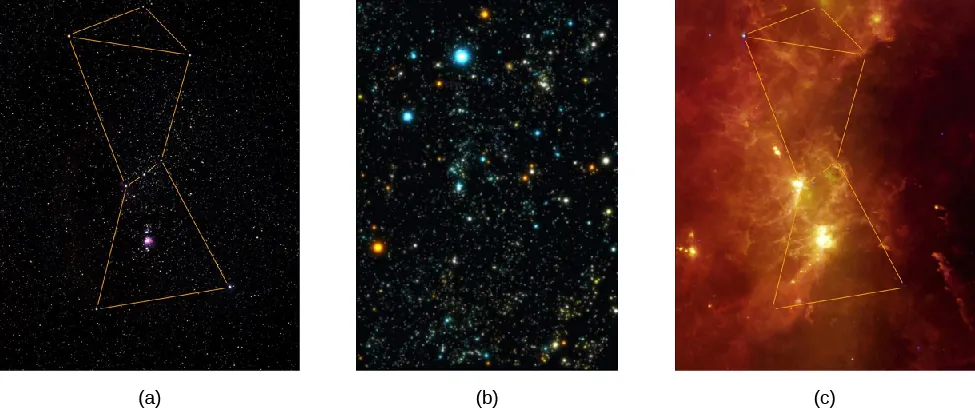
Figure 6.2 Orion Region at Different Wavelengths. The same part of the sky looks different when
observed with instruments that are sensitive to different bands of the spectrum. (a)
Visible light: this shows part of the Orion region as the human eye sees it, with dotted
lines added to show the figure of the mythical hunter, Orion. (b) X-rays: here, the view
emphasizes the point-like X-ray sources nearby. The colors are artificial, changing from
yellow to white to blue with increasing energy of the X-rays. The bright, hot stars in
Orion are still seen in this image, but so are many other objects located at very different
distances, including other stars, star corpses, and galaxies at the edge of the observable
universe. (c) Infrared radiation: here, we mainly see the glowing dust in this region. (credit
a: modification of work by Howard McCallon/NASA/IRAS; credit b: modification of
work by Howard McCallon/NASA/IRAS; credit c: modification of work by Michael F.
Corcoran)
The history of the development of astronomical telescopes is about how new technologies have
been applied to improve the efficiency of these three basic components: the telescopes, the
wavelength-sorting device, and the detectors. Let’s first look at the development of the
telescope.
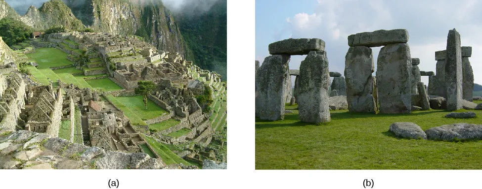
Many ancient cultures built special sites for observing the sky (Figure 6.3). At these ancient
observatories, they could measure the positions of celestial objects, mostly to keep track of time
and date. Many of these ancient observatories had religious and ritual functions as well. The eye
was the only device available to gather light, all of the colors in the light were observed at once,
and the only permanent record of the observations was made by human beings writing down or
sketching what they saw.
Figure 6.3 Two Pre-Telescopic Observatories. (a) Machu Picchu is a fifteenth century Incan site
located in Peru. (b) Stonehenge, a prehistoric site (3000–2000 BCE), is located in England. (credit
a: modification of work by Allard Schmidt)
While Hans Lippershey, Zaccharias Janssen, and Jacob Metius are all credited with the invention
of the telescope around 1608—applying for patents within weeks of each other—it was Galileo who,
in 1610, used this simple tube with lenses (which he called a spyglass) to observe the sky
and gather more light than his eyes alone could. Even his small telescope—used over
many nights—revolutionized ideas about the nature of the planets and the position of
Earth.
How Telescopes Work
Telescopes have come a long way since Galileo’s time. Now they tend to be huge devices; the most
expensive cost hundreds of millions to billions of dollars. (To provide some reference point,
however, keep in mind that just renovating college football stadiums typically costs hundreds of
millions of dollars—with the most expensive recent renovation, at Texas A&M University’s Kyle
field, costing $450 million.) The reason astronomers keep building bigger and bigger telescopes is
that celestial objects—such as planets, stars, and galaxies—send much more light to Earth than
any human eye (with its tiny opening) can catch, and bigger telescopes can detect fainter
objects.
If you have ever watched the stars with a group of friends, you know that there’s plenty of starlight
to go around; each of you can see each of the stars. If a thousand more people were watching, each
of them would also catch a bit of each star’s light. Yet, as far as you are concerned, the
light not shining into your eye is wasted. It would be great if some of this “wasted”
light could also be captured and brought to your eye. This is precisely what a telescope
does.
The most important functions of a telescope are (1) to collect the faint light from an astronomical
source and (2) to focus all the light into a point or an image. Most objects of interest to
astronomers are extremely faint: the more light we can collect, the better we can study such
objects. (And remember, even though we are focusing on visible light first, there are many
telescopes that collect other kinds of electromagnetic radiation.)
Telescopes that collect visible radiation use a lens or mirror to gather the light. Other types of
telescopes may use collecting devices that look very different from the lenses and mirrors with
which we are familiar, but they serve the same function. In all types of telescopes, the
light-gathering ability is determined by the area of the device acting as the light-gathering
“bucket.” Since most telescopes have mirrors or lenses, we can compare their light-gathering power
by comparing the apertures, or diameters, of the opening through which light travels or
reflects.
The amount of light a telescope can collect increases with the size of the aperture. A telescope with
a mirror that is 4 meters in diameter can collect 16 times as much light as a telescope that is 1
meter in diameter. (The diameter is squared because the area of a circle equals πd2∕4, where d is
the diameter of the circle.)
After the telescope forms an image, we need some way to detect and record it so that we
can measure, reproduce, and analyze the image in various ways. Before the nineteenth
century, astronomers simply viewed images with their eyes and wrote descriptions of
what they saw. This was very inefficient and did not lead to a very reliable long-term
record; you know from crime shows on television that eyewitness accounts are often
inaccurate.
In the nineteenth century, the use of photography became widespread. In those days, photographs
were a chemical record of an image on a specially treated glass plate. Today, the image is generally
detected with sensors similar to those in digital cameras, recorded electronically, and stored in
computers. This permanent record can then be used for detailed and quantitative studies.
Professional astronomers rarely look through the large telescopes that they use for their
research.
Formation of an Image by a Lens or a Mirror
Whether or not you wear glasses, you see the world through lenses; they are key elements of your
eyes. A lens is a transparent piece of material that bends the rays of light passing through it. If the
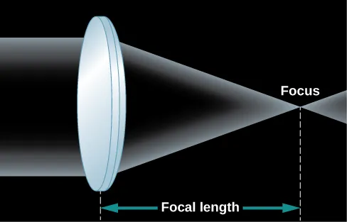
light rays are parallel as they enter, the lens brings them together in one place to form an image
(Figure 6.4).
If the curvatures of the lens surfaces are just right, all parallel rays of light (say, from a star) are
bent, or refracted, in such a way that they converge toward a point, called the focus of the lens. At
the focus, an image of the light source appears. In the case of parallel light rays, the distance from
the lens to the location where the light rays focus, or image, behind the lens is called the focal
length of the lens.
Figure 6.4 Formation of an Image by a Simple Lens. Parallel rays from a distant source are bent by
the convex lens so that they all come together in a single place (the focus) to form an
image.
As you look at Figure 6.4, you may ask why two rays of light from the same star would be parallel
to each other. After all, if you draw a picture of star shining in all directions, the rays of light
coming from the star don’t look parallel at all. But remember that the stars (and other
astronomical objects) are all extremely far away. By the time the few rays of light pointed toward
us actually arrive at Earth, they are, for all practical purposes, parallel to each other. Put another
way, any rays that were not parallel to the ones pointed at Earth are now heading in some very
different direction in the universe.
To view the image formed by the lens in a telescope, we use an additional lens called an eyepiece.
The eyepiece focuses the image at a distance that is either directly viewable by a human
or at a convenient place for a detector. Using different eyepieces, we can change the
magnification (or size) of the image and also redirect the light to a more accessible
location. Stars look like points of light, and magnifying them makes little difference, but
the image of a planet or a galaxy, which has structure, can often benefit from being
magnified.
Many people, when thinking of a telescope, picture a long tube with a large glass lens at one end.
This design, which uses a lens as its main optical element to form an image, as we have been
discussing, is known as a refractor (Figure 6.5), and a telescope based on this design is called a
refracting telescope. Galileo’s telescopes were refractors, as are today’s binoculars and field glasses.
However, there is a limit to the size of a refracting telescope. The largest one ever built was a
49-inch refractor built for the Paris 1900 Exposition, and it was dismantled after the Exposition.
Currently, the largest refracting telescope is the 40-inch refractor at Yerkes Observatory in
Wisconsin.
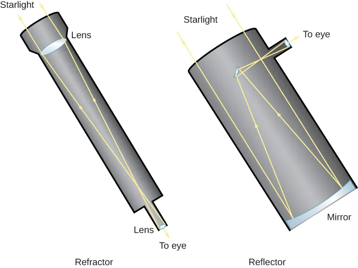
Figure 6.5 Refracting and Reflecting Telescopes. Light enters a refracting telescope through a lens
at the upper end, which focuses the light near the bottom of the telescope. An eyepiece then
magnifies the image so that it can be viewed by the eye, or a detector like a photographic plate
can be placed at the focus. The upper end of a reflecting telescope is open, and the
light passes through to the mirror located at the bottom of the telescope. The mirror
then focuses the light at the top end, where it can be detected. Alternatively, as in this
sketch, a second mirror may reflect the light to a position outside the telescope structure,
where an observer can have easier access to it. Professional astronomers’ telescopes
are more complicated than this, but they follow the same principles of reflection and
refraction.
One problem with a refracting telescope is that the light must pass through the lens of a refractor.
That means the glass must be perfect all the way through, and it has proven very difficult to make
large pieces of glass without flaws and bubbles in them. Also, optical properties of transparent
materials change a little bit with the wavelengths (or colors) of light, so there is some additional
distortion, known as chromatic aberration. Each wavelength focuses at a slightly different spot,
causing the image to appear blurry.
In addition, since the light must pass through the lens, the lens can only be supported around its
edges (just like the frames of our eyeglasses). The force of gravity will cause a large lens to sag and
distort the path of the light rays as they pass through it. Finally, because the light passes through
it, both sides of the lens must be manufactured to precisely the right shape in order to produce a
sharp image.
A different type of telescope uses a concave primary mirror as its main optical element. The mirror
is curved like the inner surface of a sphere, and it reflects light in order to form an image (Figure
6.5). Telescope mirrors are coated with a shiny metal, usually silver, aluminum, or, occasionally,
gold, to make them highly reflective. If the mirror has the correct shape, all parallel rays are
reflected back to the same point, the focus of the mirror. Thus, images are produced by a mirror
exactly as they are by a lens.
Telescopes designed with mirrors avoid the problems of refracting telescopes. Because
the light is reflected from the front surface only, flaws and bubbles within the glass do
not affect the path of the light. In a telescope designed with mirrors, only the front
surface has to be manufactured to a precise shape, and the mirror can be supported from
the back. For these reasons, most astronomical telescopes today (both amateur and
professional) use a mirror rather than a lens to form an image; this type of telescope is called a
reflecting telescope. The first successful reflecting telescope was built by Isaac Newton in
1668.
In a reflecting telescope, the concave mirror is placed at the bottom of a tube or open framework.
The mirror reflects the light back up the tube to form an image near the front end at a location
called the prime focus. The image can be observed at the prime focus, or additional mirrors can
intercept the light and redirect it to a position where the observer can view it more easily (Figure
6.6). Since an astronomer at the prime focus can block much of the light coming to the
main mirror, the use of a small secondary mirror allows more light to get through the
system.
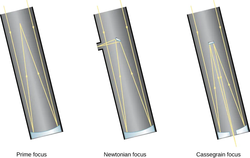
Figure 6.6 Focus Arrangements for Reflecting Telescopes. Reflecting telescopes have different
options for where the light is brought to a focus. With prime focus, light is detected where it comes
to a focus after reflecting from the primary mirror. With Newtonian focus, light is reflected by a
small secondary mirror off to one side, where it can be detected (see also Figure 6.5). Most large
professional telescopes have a Cassegrain focus in which light is reflected by the secondary
mirror down through a hole in the primary mirror to an observing station below the
telescope.
Making Connections
Choosing Your Own Telescope
If the astronomy course you are taking whets your appetite for exploring the sky further, you may
be thinking about buying your own telescope. Many excellent amateur telescopes are available, and
some research is required to find the best model for your needs. Some good sources of information
about personal telescopes are the two popular US magazines aimed at amateur astronomers: Sky &
Telescope and Astronomy. Both carry regular articles with advice, reviews, and advertisements
from reputable telescope dealers.
Some of the factors that determine which telescope is right for you depend upon your preferences:
- Will you be setting up the telescope in one place and leaving it there, or do you want
an instrument that is portable and can come with you on outdoor excursions? How
portable should it be, in terms of size and weight?
- Do you want to observe the sky with your eyes only, or do you want to take
photographs? (Long-exposure photography, for example, requires a good clock drive to
turn your telescope to compensate for Earth’s rotation.)
- What types of objects will you be observing? Are you interested primarily in comets,
planets, star clusters, or galaxies, or do you want to observe all kinds of celestial sights?
You may not know the answers to some of these questions yet. For this reason, you may want to
“test-drive” some telescopes first. Most communities have amateur astronomy clubs that sponsor
star parties open to the public. The members of those clubs often know a lot about telescopes and
can share their ideas with you. Your instructor may know where the nearest amateur
astronomy club meets; or, to find a club near you, use the websites suggested in Appendix
B.
Furthermore, you may already have an instrument like a telescope at home (or have access to one
through a relative or friend). Many amateur astronomers recommend starting your survey of the
sky with a good pair of binoculars. These are easily carried around and can show you many objects
not visible (or clear) to the unaided eye.
When you are ready to purchase a telescope, you might find the following ideas useful:
- The key characteristic of a telescope is the aperture of the main mirror or lens; when
someone says they have a 6-inch or 8-inch telescope, they mean the diameter of the
collecting surface. The larger the aperture, the more light you can gather, and the
fainter the objects you can see or photograph.
- Telescopes of a given aperture that use lenses (refractors) are typically more expensive
than those using mirrors (reflectors) because both sides of a lens must be polished to
great accuracy. And, because the light passes through it, the lens must be made of
high-quality glass throughout. In contrast, only the front surface of a mirror must be
accurately polished.
- Magnification is not one of the criteria on which to base your choice of a telescope.
As we discussed, the magnification of the image is done by a smaller eyepiece, so the
magnification can be adjusted by changing eyepieces. However, a telescope will magnify
not only the astronomical object you are viewing but also the turbulence of Earth’s
atmosphere. If the magnification is too high, your image will shimmer and shake and
be difficult to view. A good telescope will come with a variety of eyepieces that stay
within the range of useful magnification.
- The mount of a telescope (the structure on which it rests) is one of its most critical
elements. Because a telescope shows a tiny field of view, which is magnified significantly,
even the smallest vibration or jarring of the telescope can move the object you are
viewing around or out of your field of view. A sturdy and stable mount is essential for
serious viewing or photography (although it clearly affects how portable your telescope
can be).
- A telescope requires some practice to set up and use effectively. Don’t expect everything
to go perfectly on your first try. Take some time to read the instructions. If a local
amateur astronomy club is nearby, use it as a resource.
Attribution
Doppler effect (Definition) Astronomers can learn about the elements in stars and galaxies by
decoding the information in their spectral lines. There is a complicating factor in learning how to
decode the message of starlight, however. If a star is moving toward or away from us, its
lines will be in a slightly different place in the spectrum from where they would be in
a star at rest. And most objects in the universe do have some motion relative to the
Sun.
Motion Affects Waves
In 1842, Christian Doppler first measured the effect of motion on waves by hiring a group of
musicians to play on an open railroad CAR as it was moving along the track. He then applied what
he learned to all waves, including light, and pointed out that if a light source is approaching or
receding from the observer, the light waves will be, respectively, crowded more closely together or
spread out. The general principle, now known as the Doppler effect, is illustrated in Figure
5.22.
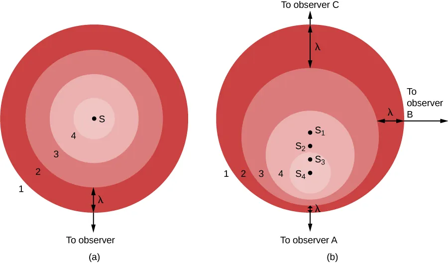
Figure 5.22 Doppler Effect. (a) A source, S, makes waves whose numbered crests (1, 2, 3, and 4)
wash over a stationary observer. (b) The source S now moves toward observer A and away from
observer C. Wave crest 1 was emitted when the source was at position S1, crest 2 at position S2,
and so forth. Observer A sees waves compressed by this motion and sees a blueshift (if the waves
are light). Observer C sees the waves stretched out by the motion and sees a redshift. Observer B,
whose line of sight is perpendicular to the source’s motion, sees no change in the waves (and feels
left out).
In part (a) of the figure, the light source (S) is at rest with respect to the observer. The source
gives off a series of waves, whose crests we have labeled 1, 2, 3, and 4. The light waves spread
out evenly in all directions, like the ripples from a splash in a pond. The crests are
separated by a distance, λ, where λ is the wavelength. The observer, who happens to be
located in the direction of the bottom of the image, sees the light waves coming nice
and evenly, one wavelength apart. Observers located anywhere else would see the same
thing.
On the other hand, if the source of light is moving with respect to the observer, as seen in part (b),
the situation is more complicated. Between the time one crest is emitted and the next one is ready
to come out, the source has moved a bit, toward the bottom of the page. From the point of view of
observer A, this motion of the source has decreased the distance between crests—it’s squeezing the
crests together, this observer might say.
In part (b), we show the situation from the perspective of three observers. The source is seen
in four positions, S1, S2, S3, and S4, each corresponding to the emission of one wave
crest. To observer A, the waves seem to follow one another more closely, at a decreased
wavelength and thus increased frequency. (Remember, all light waves travel at the speed of
light through empty space, no matter what. This means that motion cannot affect the
speed, but only the wavelength and the frequency. As the wavelength decreases, the
frequency must increase. If the waves are shorter, more will be able to move by during each
second.)
The situation is not the same for other observers. Let’s look at the situation from the point of view
of observer C, located opposite observer A in the figure. For her, the source is moving away from
her location. As a result, the waves are not squeezed together but instead are spread out by the
motion of the source. The crests arrive with an increased wavelength and decreased frequency.
To observer B, in a direction at right angles to the motion of the source, no effect is
observed. The wavelength and frequency remain the same as they were in part (a) of the
figure.
We can see from this illustration that the Doppler effect is produced only by a motion toward or
away from the observer, a motion called radial velocity. Sideways motion does not produce such an
effect. Observers between A and B would observe some shortening of the light waves
for that part of the motion of the source that is along their line of sight. Observers
between B and C would observe lengthening of the light waves that are along their line of
sight.
You may have heard the Doppler effect with sound waves. When a train whistle or police siren
approaches you and then moves away, you will notice a decrease in the pitch (which is how human
senses interpret sound wave frequency) of the sound waves. Compared to the waves at rest, they
have changed from slightly more frequent when coming toward you, to slightly less frequent when
moving away from you.
Link to Learning
A nice example of this change in the sound of a train whistle can be heard at the end of the classic
Beach Boys song “Caroline, No” on their album PET Sounds. To hear this sound, go to this
YouTube (https://openstax.org/l/30BBtrain) version of the song. The sound of the train begins at
approximately 2:20.
Color Shifts
When the source of waves moves toward you, the wavelength decreases a bit. If the waves involved
are visible light, then the colors of the light change slightly. As wavelength decreases, they shift
toward the blue end of the spectrum: astronomers call this a blueshift (since the end
of the spectrum is really violet, the term should probably be violetshift, but blue is
a more common color). When the source moves away from you and the wavelength
gets longer, we call the change in colors a redshift. Because the Doppler effect was first
used with visible light in astronomy, the terms “blueshift” and “redshift” became well
established. Today, astronomers use these words to describe changes in the wavelengths of
radio waves or X-rays as comfortably as they use them to describe changes in visible
light.
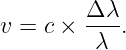
The greater the motion toward or away from us, the greater the Doppler shift. If the
relative motion is entirely along the line of sight, the formula for the Doppler shift of light
is
where λ is the wavelength emitted by the source, Δλ is the difference between λ and the
wavelength measured by the observer, c is the speed of light, and v is the relative speed of the
observer and the source in the line of sight. The variable v is counted as positive if the velocity is
one of recession, and negative if it is one of approach. Solving this equation for the velocity, we
find
Link to Learning
Click-and-drag the object emitting waves or the object receiving waves in this simulator
(https://openstax.org/l/30doppsim) to experiment with the Doppler effect yourself. The plots
along the top show how the detected wavelengths change if the objects are approaching each other
or moving further apart.
If a star approaches or recedes from us, the wavelengths of light in its continuous spectrum appear
shortened or lengthened, respectively, as do those of the dark lines. However, unless its speed is
tens of thousands of kilometers per second, the star does not appear noticeably bluer or redder
than normal. The Doppler shift is thus not easily detected in a continuous spectrum and cannot
be measured accurately in such a spectrum. The wavelengths of the absorption lines
can be measured accurately, however, and their Doppler shift is relatively simple to
detect.
You may now be asking: if all the stars are moving and motion changes the wavelength of
each spectral line, won’t this be a disaster for astronomers trying to figure out what
elements are present in the stars? After all, it is the precise wavelength (or color) that tells
astronomers which lines belong to which element. And we first measure these wavelengths in
containers of gas in our laboratories, which are not moving. If every line in a star’s
spectrum is now shifted by its motion to a different wavelength (color), how can we be
sure which lines and which elements we are looking at in a star whose speed we do not
know?
Take heart. This situation sounds worse than it really is. Astronomers rarely judge the presence of
an element in an astronomical object by a single line. It is the pattern of lines unique
to hydrogen or calcium that enables us to determine that those elements are part of
the star or galaxy we are observing. The Doppler effect does not change the pattern
of lines from a given element—it only shifts the whole pattern slightly toward redder
or bluer wavelengths. The shifted pattern is still quite easy to recognize. Best of all,
when we do recognize a familiar element’s pattern, we get a bonus: the amount the
pattern is shifted can enable us to determine the speed of the objects in our line of
sight.
The training of astronomers includes much work on learning to decode light (and other
electromagnetic radiation). A skillful “decoder” can learn the temperature of a star, what elements
are in it, and even its speed in a direction toward us or away from us. That’s really an impressive
amount of information for stars that are light-years away.
Attribution
Access for free at openstax.org.
Bibliography
This article is a derivative work of the original 2022 CC BY 4.0 release identified in
[1].
[1] Andrew Fraknoi, David Morrison, and Sidney Wolff, “6.1 Telescopes,” in Astronomy 2e.
Houston, Texas: OpenStax, March 9, 2022. Original digital ISBN 978-1-951693-50-3. Original
textbook content licensed under the Creative Commons Attribution 4.0 International License (CC
BY 4.0), except where otherwise noted. Changes: converted to LaTeX for PhysicsLibrary. Access
for free at openstax.org.