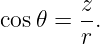
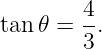
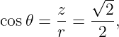
Coordinate Systems for Mechanics
A coordinate system is a mathematical scheme for assigning numbers to positions and directions.
The physical motion does not depend on which coordinates are chosen, but a good coordinate
system can make the geometry, constraints, and equations of a mechanics problem much
simpler.
The central principle is therefore not that one coordinate system is more “correct” than another.
Instead,
Cartesian coordinates are natural for straight-line motion, projectiles, rectangular geometry, and
many Free-body diagrams. Polar and cylindrical coordinates are natural when distance
from an axis and rotation about that axis are important. Spherical coordinates are
natural when distance from a point is the dominant geometric variable, as in central-force
problems.
This article develops the geometry needed to use these systems in mechanics without yet deriving
the full velocity and acceleration formulas of curvilinear kinematics. Those derivatives belong to
later kinematics articles.
1 Coordinate system versus reference frame
A coordinate system and a reference frame are related but distinct ideas.
A reference frame identifies the physical observer or laboratory whose origin and axes have a
specified motion. A coordinate system is the mathematical labeling used inside that
frame.
For example, one inertial laboratory frame may describe a particle using Cartesian coordinates
(x,y,z) or cylindrical coordinates (ρ,ϕ,z). Changing from one of those coordinate systems to the
other does not by itself create a new physical observer.
This distinction becomes important later when mechanics is written in accelerating or rotating
reference frames.
2 Cartesian coordinates
In a three-dimensional Cartesian coordinate system, mutually perpendicular axes define fixed unit
vectors
A position vector is
The coordinates x, y, and z are signed distances measured along the three axes.
Because the Cartesian basis vectors are fixed in orientation, they are especially convenient when
differentiating vector components with respect to time.
The infinitesimal displacement is
and the differential distance satisfies
2.1 Rotated Cartesian axes
The axes need not be horizontal and vertical. In an inclined-plane problem, for example, it is often
convenient to choose one Cartesian axis parallel to the incline and another normal to
it.
If a new x′ axis is rotated counterclockwise through an angle α from the original x axis,
then
and
For a vector
the components in the rotated basis are
The geometric vector is unchanged; only its numerical components have changed.
3 Plane polar coordinates
For two-dimensional problems with circular or radial geometry, a point may be described
by
where r is the nonnegative distance from the origin and 𝜃 is the angular coordinate measured from
the positive x axis.
The Cartesian and polar coordinates are related by
Conversely,
and the angle should be determined with the signs of both x and y taken into account.
Computationally, a quadrant-aware two-argument arctangent is preferred.
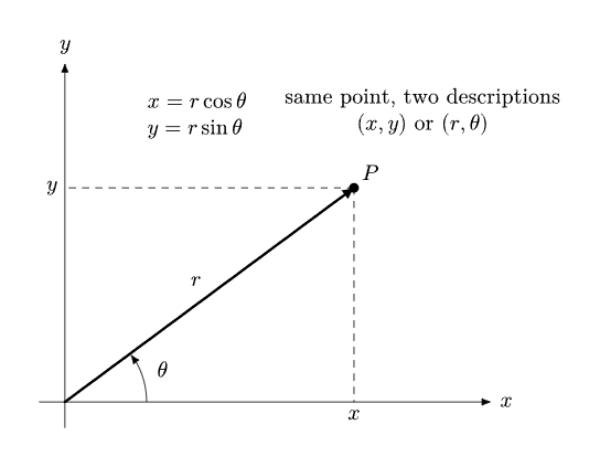
Figure 1. The same physical point may be represented by Cartesian coordinates (x,y) or polar
coordinates (r,𝜃).
3.1 The polar basis
Polar coordinates use position-dependent unit vectors. The radial unit vector points away from the
origin,
and the transverse unit vector points in the direction of increasing 𝜃,
The position vector is particularly simple:
Unlike ex and ey, the polar basis vectors change direction when 𝜃 changes. This fact is responsible
for important extra terms when velocity and acceleration are differentiated in polar coordinates.
Those terms are geometric consequences of the moving basis, not fictitious forces created merely by
choosing polar coordinates.
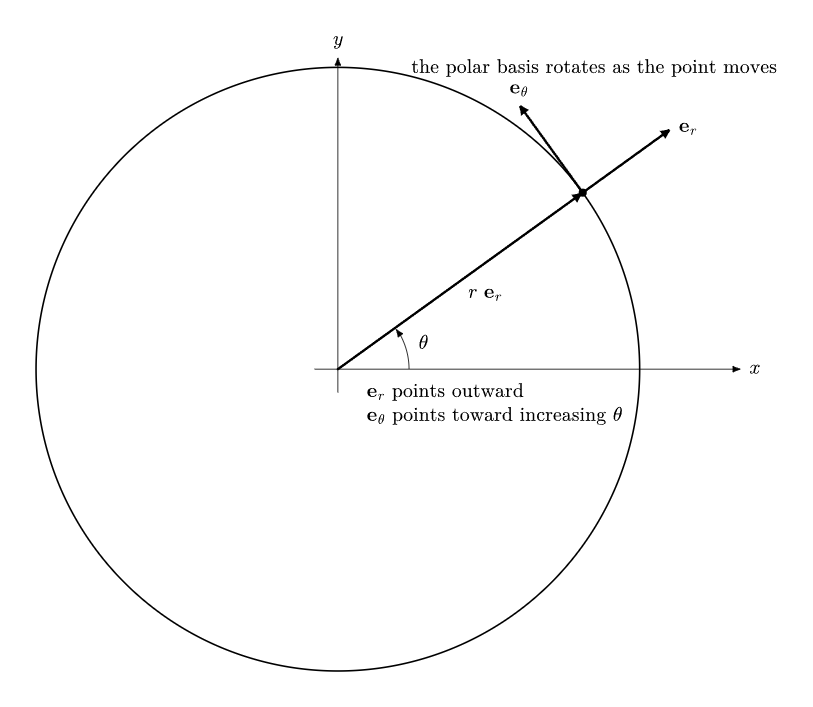
Figure 2. The polar basis is attached locally to the point. As the angular coordinate changes, er
and e𝜃 rotate.
4 Deriving the polar differential displacement
The geometry of polar coordinates becomes especially clear by differentiating the coordinate
transformation. Starting with
we obtain
Similarly,
Insert these into
Collecting terms gives
The two perpendicular differential distances are therefore
and
Hence
For motion along a circle of fixed radius,
so
The angle must be expressed in radians for this differential arc-length relation.
5 Cylindrical coordinates
Cylindrical coordinates extend plane polar coordinates by retaining an independent vertical
coordinate:
Here ρ is distance from the z axis, ϕ is the azimuth about the z axis, and z is the usual Cartesian
height.
The transformation is
Conversely,
The local basis is
and the differential displacement is
Therefore
The differential volume is
The factor ρ is geometric: an angular increment dϕ corresponds to a longer physical arc when the
point lies farther from the axis.
Cylindrical coordinates are useful for shafts, disks, cylinders, circular or helical motion, and
systems with symmetry about an axis.
6 Spherical coordinates
Spherical coordinates are natural for problems centered on a point. Several notation conventions
exist, so every article or problem should state its convention explicitly.
This mechanics article uses
where
- r is distance from the origin;
- 𝜃 is the polar angle measured downward from the positive z axis;
- ϕ is the azimuth measured in the xy plane from the positive x axis.
The Cartesian transformation is
Conversely,
The azimuth ϕ is determined from x and y with quadrant information retained.
The differential displacement is
Thus
and the differential volume is
Spherical coordinates are especially useful for gravitational and other central-force fields, spherical
bodies, and three-dimensional systems with symmetry about a point.
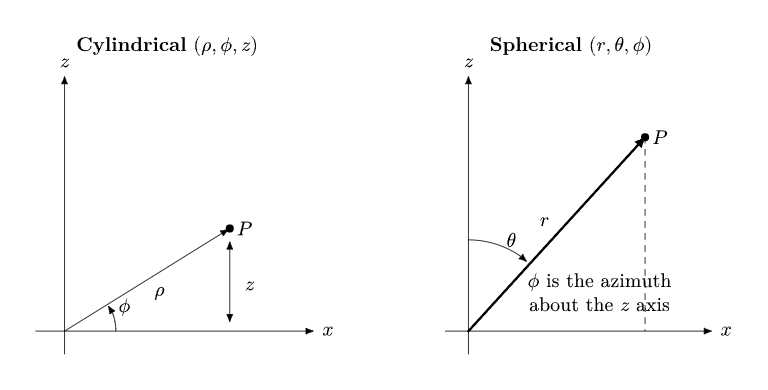
Figure 3. Cylindrical coordinates organize geometry about an axis, while spherical coordinates
organize geometry about a point. The spherical-angle convention must always be stated.
7 Scale factors and orthogonal curvilinear coordinates
Cartesian, polar, cylindrical, and spherical coordinates are all examples of orthogonal coordinate
systems: their local basis directions are mutually perpendicular.
A useful general form for the differential distance is
where the quantities hi are called scale factors.
For Cartesian coordinates,
For cylindrical coordinates,
For the spherical convention used here,
These factors encode how a coordinate increment translates into an actual physical distance. They
later enter velocity, acceleration, gradients, divergence, curl, and volume integration in curvilinear
coordinates.
8 Worked example 1: Cartesian to polar
A point in the plane has Cartesian coordinates
Find its polar coordinates.
The radial coordinate is
so
The point lies in the first quadrant, and
Therefore
Thus the same point may be written
9 Worked example 2: Cartesian to cylindrical
A point has Cartesian coordinates
Find its cylindrical coordinates.
The distance from the z axis is
Because x < 0 and y > 0, the point is in the second quadrant of the xy plane. The azimuth is
therefore
The vertical coordinate is unchanged:
Hence
10 Worked example 3: Cartesian to spherical
A point has coordinates
Using the spherical convention of this article, find (r,𝜃,ϕ).
First,
Next,
so
Since x = y > 0,
Thus
11 Worked example 4: choose axes that follow an incline
A 2.00 kg block rests on a frictionless plane inclined at
above the horizontal. Choose a rotated Cartesian basis with +x′ up the incline and +y′ outward
normal to the surface. Resolve the weight into this basis.
The weight magnitude is
The component along the incline is opposite +x′:
Thus
The normal component points into the plane, opposite +y′:
Therefore
The physics has not changed. The coordinate choice simply aligns the components with the natural
directions of the constraint.
12 How to choose a coordinate system
A useful coordinate system usually reflects either a geometric constraint or a symmetry.
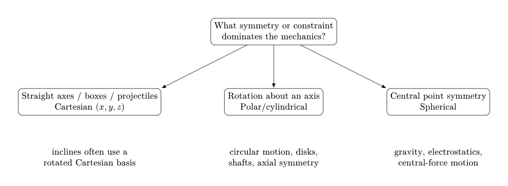
Figure 4. Coordinate choice should follow the geometry or symmetry of the mechanics problem.
Typical choices include:
- Cartesian coordinates for projectiles, blocks, straight tracks, and rectangular
geometries;
- rotated Cartesian coordinates for inclined planes or motion constrained along a straight
line;
- polar coordinates for planar rotation or central motion;
- cylindrical coordinates for rotation about an axis, disks, cylinders, and helical paths;
- spherical coordinates for gravitational or other central fields and spherical bodies.
A good choice often reduces the number of nonzero components or turns a constraint into the
statement that one coordinate is constant.
13 Coordinate singularities
Curvilinear coordinate systems contain locations where one or more coordinates become
ambiguous.
At r = 0 in polar coordinates, the angle 𝜃 is undefined. In cylindrical coordinates, ϕ is undefined on
the z axis. In spherical coordinates, the azimuth ϕ is undefined at the poles, and both angles are
undefined at the origin.
These are often coordinate singularities, not singularities in the underlying physical space. A
particle can pass smoothly through the origin even though polar coordinates temporarily become a
poor description there.
14 Coordinates, components, and basis vectors
Three related ideas should not be confused:
- coordinates label the location of a point;
- components are numerical coefficients of a vector relative to a basis;
- basis vectors specify the directions used to construct the vector.
In Cartesian coordinates, the position coordinates and the coefficients in
happen to look very similar. In spherical coordinates the position vector is instead simply
even though three coordinates (r,𝜃,ϕ) are needed to locate the point. The angles determine the
direction of er rather than appearing as separate additive components of r.
15 Preview: from coordinates to kinematics
When coordinates depend on time, the position becomes
In Cartesian coordinates the basis is fixed, while in polar, cylindrical, and spherical coordinates the
local basis changes direction as the particle moves.
This distinction produces the characteristic radial and transverse terms in curvilinear velocity and
acceleration. Later articles derive, for example, the polar-coordinate velocity
and the corresponding acceleration. Those are kinematic consequences of differentiating both the
coordinates and the moving basis vectors.
At a still more general level, analytical mechanics uses generalized coordinates chosen to match the
degrees of freedom and constraints of a system. Cartesian, cylindrical, and spherical coordinates
are important examples, but they are not the end of the idea.
16 Common mistakes
- Confusing a coordinate system with a reference frame. A coordinate
transformation need not represent a different observer.
- Using a one-argument arctangent without checking the quadrant. The ratio
y∕x alone does not identify the correct angle.
- Mixing spherical conventions. Some texts interchange the symbols 𝜃 and ϕ. State
the convention before calculating.
- Treating curvilinear basis vectors as fixed. er, e𝜃, eρ, and eϕ change direction
with position.
- Using degrees in differential arc formulas. Relations such as ds = r d𝜃 assume
radians.
- Mistaking coordinate singularities for physical singularities. An undefined
angular coordinate may reflect only a poor labeling at that point.
17 Practice problems
MECH-COORD-001 — Choose the natural coordinates
For each system, identify a natural coordinate system and explain why: (a) a projectile near
Earth’s surface, (b) a bead constrained to a circular hoop in a plane, and (c) a particle moving in a
central gravitational field.
MECH-COORD-002 — Cartesian to polar
Convert
to polar coordinates.
MECH-COORD-003 — Polar to Cartesian
Convert
to Cartesian coordinates.
MECH-COORD-004 — Cylindrical to Cartesian
Convert
to Cartesian coordinates.
MECH-COORD-005 — Cartesian to spherical
Using the convention of this article, convert
to spherical coordinates.
MECH-COORD-006 — Arc length in polar coordinates
A particle moves along a circle of radius 2.00 m through an angular increment of 0.300 rad. Find
the path length.
MECH-COORD-007 — Differential distance in cylindrical coordinates
At ρ = 3.00 m, a small coordinate change is
Estimate ds.
MECH-COORD-008 — Differential distance in spherical coordinates
At r = 4.00 m and 𝜃 = 60∘, let
Estimate ds.
MECH-COORD-009 — Cylindrical volume element
At ρ = 2.00 m, estimate the volume of a small cylindrical-coordinate cell with
MECH-COORD-010 — Gravity in incline coordinates
A 5.00 kg block lies on a plane inclined at 20∘. Choose +x′ up the plane and +y′ outward normal
to it. Find the two components of the weight using g = 9.80 m/s2.
18 Short answer key
- (a) Cartesian; (b) polar; (c) spherical.
- r = 4.243 m, 𝜃 = 135∘.
- x = −3.464 m, y = −2.000 m.
- x ≈ 3.00 m, y ≈ 4.00 m, z = −2.00 m.
- r = 2
 = 2.828 m, 𝜃 = 45∘, ϕ = 120∘.
- s = 0.600 m.
- ds ≈ 0.122 m.
- ds ≈ 0.132 m.
- dV = 0.00200 m3.
- Wx′ = −16.8 N, Wy′ = −46.0 N.
19 Connections to later mechanics
Coordinate systems are used throughout the mechanics learning path. The next foundations article
distinguishes coordinate descriptions from physical reference frames. Later kinematics articles
derive velocity and acceleration in polar, cylindrical, and spherical coordinates. Central-force
mechanics, rotating frames, rigid-body dynamics, and Lagrangian mechanics all rely on the
coordinate ideas introduced here.
References
[1] OpenStax, University Physics Volume 1, archived 2016 revision hosted by BCcampus,
CC BY 4.0.
[2] T. Weideman, UCD Physics 9A: Classical Mechanics, University of California, Davis
/ LibreTexts, CC BY-SA 4.0.
[3] Wikibooks contributors, Classical Mechanics, CC BY-SA.
[4] J. R. Taylor, Classical Mechanics, University Science Books, 2005.