Pulleys and Atwood Machines
A pulley changes the direction of a string and, in some arrangements, changes the relation between
the motions and forces of connected bodies. The central ideas are not new force laws. They are the
same tension model and Newton’s second law developed earlier, combined with a geometric
constraint from an inextensible string.
For an ideal pulley system, three modeling assumptions are especially important:
- the string is massless, so an ideal continuous string can have one tension magnitude
when no other tangential interaction changes it;
- the string is inextensible, so its total length is fixed and the coordinates of the attached
bodies are constrained;
- the pulley is ideal, meaning its axle is frictionless and its Rotational Inertia is neglected
unless stated otherwise.
The first assumption controls force transmission. The second controls kinematics. The third
determines whether the tension magnitude can remain the same on the two sides of a
pulley.
1 What an ideal fixed pulley does
A fixed pulley is attached to a support and does not translate. Its primary role is to redirect the
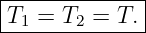
string. For an ideal fixed pulley, the tension magnitude is the same on both sides of one continuous
massless string:
This equality is not a general property of every real pulley. A pulley with appreciable rotational
inertia or axle friction can require different tensions on its two sides. The ideal result is a model
assumption justified by neglecting those effects.
A single fixed pulley also does not provide a force advantage. In a static arrangement
where one end supports a load of Weight W, the other end must sustain the same ideal
tension,
Its advantage is directional: a downward pull on one end can raise a load on the other.
2 The fixed length constraint
Consider a single inextensible string passing over a fixed pulley. Let x1 and x2 be downward
coordinates measured from fixed points near the pulley. Apart from the constant length wrapped
around the pulley,
where C is constant.
Because the total length L is fixed,
Differentiating with respect to time gives
and differentiating again gives
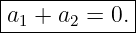
Thus the two ends have equal speed magnitudes and equal acceleration magnitudes, but they move
in opposite directions when the same downward coordinate convention is used on both
sides.
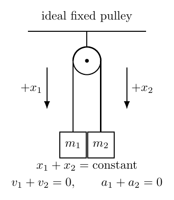
Figure 1. For one inextensible string over an ideal fixed pulley, x1 + x2 is constant. The velocity
and acceleration components measured downward on the two sides therefore sum to zero.
If instead the positive axis for each body is chosen along its actual direction of motion, both scalar
acceleration equations may use the same positive symbol a. This is only a coordinate choice. The
underlying vector accelerations still point in opposite directions.
3 The Atwood machine
The classic Atwood machine consists of two masses connected by one light inextensible string over
an ideal fixed pulley. Let
Then m2 accelerates downward while m1 accelerates upward. Because the string is inextensible,
both acceleration magnitudes are the same. Let that magnitude be a.
For m1, choose upward positive:
For m2, choose downward positive:
Adding the equations eliminates the internal tension:
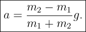
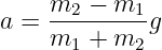
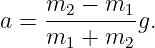
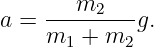
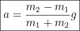
Therefore
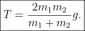
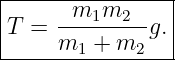
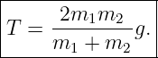
Substituting into either mass equation gives the tension
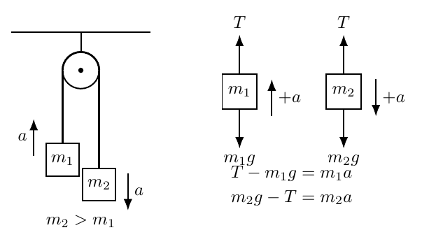
Figure 2. Atwood machine and separate free body diagrams. With m2 > m1, the heavier mass
accelerates downward and the lighter mass accelerates upward with the same magnitude a.
4 Physical checks on the Atwood result
The formula
contains several useful checks.
If m1 = m2, then
Equal masses balance, and the tension is simply
If m1 → 0 while m2 remains finite, then
and
The remaining mass approaches free fall because the opposite side contributes almost no inertia or
tension.
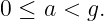
For positive finite masses,
An ideal Atwood mass cannot accelerate faster than free fall.
5 Why adding the two equations works
For the two mass system, the two tension forces are internal. They are equal in magnitude and
opposite in their effect on the system coordinate. Adding the two Newton equations removes the
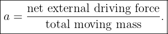
internal force and leaves only the net external driving force,
The total inertial mass being accelerated is
This gives the compact system interpretation
The tension is then recovered by isolating one body.
6 A block on a table connected to a hanging mass
A second standard arrangement places one block of mass m1 on a frictionless horizontal table and
connects it over an ideal fixed pulley to a hanging mass m2.
Because one inextensible string connects the two bodies, their acceleration magnitudes are equal.
For the block on the table,
For the hanging mass, taking downward positive,
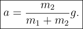
Adding gives
so
The tension is
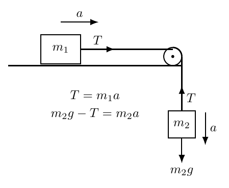
Figure 3. A block on a frictionless table connected to a hanging mass. The fixed length string
gives the same acceleration magnitude for the horizontal and vertical motions.
This system is not an Atwood machine in the strict two hanging mass sense, but it uses the same
modeling pattern: string constraint, equal ideal tension, and one Newton equation for each
body.
7 Movable pulleys change the kinematic ratio
A movable pulley translates with the load. This changes the string length relation.
Consider one end of a string fixed to the ceiling. The string descends around a movable pulley and
then rises to a free end. Let yp be the downward coordinate of the movable pulley and yf the
downward coordinate of the free end.
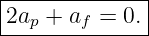
Two variable string segments change length when the movable pulley moves. Therefore
Differentiating,
and
The free end therefore moves twice as far and twice as fast as the movable pulley, in the opposite
direction when both coordinates are measured downward.
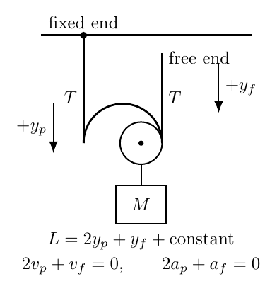
Figure 4. A single movable pulley is supported by two segments of the same ideal string. The
length relation is L = 2yp + yf + C, so the free end moves twice as far as the pulley.
8 Force support from a movable pulley
The same ideal string passes around the movable pulley, so each supporting segment has tension
magnitude T. The pulley and attached load therefore receive two upward tension forces. Neglecting
the mass of the pulley itself, the upward support is
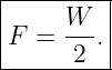
For static equilibrium of a load with weight W,
Hence
If a person pulls the free end with force magnitude F = T, the ideal equilibrium force needed
is
The price for this force advantage is displacement: the free end must move twice as far as the
load.
More generally, in a simple ideal arrangement where a moving load is supported by n segments of
the same rope, static force balance often gives
so the ideal force advantage is associated with the number of supporting rope segments. The exact
kinematic relation must still be derived from the actual rope geometry rather than memorized from
the number n alone.
9 Constraint equations should be derived from geometry
Pulley problems become unreliable when acceleration relations are guessed. The safe procedure is
to write the total length of each inextensible string explicitly.
For example, if one string contains variable straight segments s1, s2, and s3, then
Because L is constant,
and
These derivatives produce the velocity and acceleration constraints. Fixed portions of rope,
fixed pulley wrap lengths, and constant offsets are absorbed into C and disappear upon
differentiation.
10 When tensions are not equal
The equality of tension on the two sides of a pulley is an idealization. If the pulley has
appreciable rotational inertia, the two string tensions generally differ because a net torque is
required to angularly accelerate the pulley. If axle friction is present, the tensions can also
differ.
Those cases require rotational dynamics. They are not part of the ideal translational model
developed here. The important diagnostic is:
Different strings should still be given different tension symbols unless the equations prove
otherwise.
11 A systematic procedure for pulley problems
- Identify each distinct string and each pulley that moves.
- State the idealizations: massless string, inextensible string, ideal pulley, and any
frictionless surfaces.
- Choose coordinates for every moving body and pulley.
- Write one fixed length equation for each inextensible string.
- Differentiate the length equation to obtain the velocity or acceleration constraints.
- Draw a separate free body diagram for each body or useful combined system.
- Use one tension symbol along a single ideal string passing over ideal pulleys; use
different symbols for different strings.
- Apply Newton’s second law with a consistent sign convention.
- Solve the force equations together with the kinematic constraints.
- Check limiting cases, directions, and whether the assumed string remains taut.
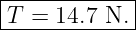
12 Worked example 1: a basic Atwood machine
Two masses
are connected by a massless inextensible string over an ideal fixed pulley. Find the acceleration
magnitude and the tension.
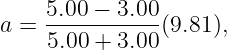
The acceleration is
Substituting,
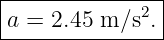
so
The 5.00 kg mass accelerates downward and the 3.00 kg mass accelerates upward.
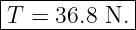
Using
we obtain
so
13 Worked example 2: a table and hanging mass
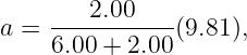
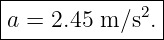
A 6.00 kg block rests on a frictionless table and is connected over an ideal pulley to a hanging 2.00
kg mass. Find the acceleration magnitude and tension.
The system acceleration is
Therefore
which gives
For the block on the table,
so
14 Worked example 3: an ideal movable pulley
A load has weight
and is supported by a single ideal movable pulley. One end of the rope is fixed to the ceiling and a
person pulls the free end. Find the required force for static equilibrium and the free end
displacement needed to raise the load by 0.250 m.
Two rope segments support the movable pulley, so
Thus
The person’s pull equals the rope tension in the ideal model:
For the string length,
If the pulley and load move upward by 0.250 m, then with downward positive
Therefore
The person must pull the free end downward by
The ideal force is halved while the input displacement is doubled.
15 Worked example 4: a hanging mass driving a movable pulley
A 4.00 kg mass m1 hangs from the free end of an ideal rope. The same rope passes
around a massless movable pulley that supports a 6.00 kg load m2. The other end of
the rope is fixed to the ceiling. Determine the acceleration of each mass and the rope
tension.
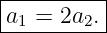
Let a1 be positive downward for m1, and let a2 be positive upward for the movable pulley and load.
From the length constraint,
For the hanging mass,
For the movable pulley and attached load, two rope segments pull upward:
Using a1 = 2a2 in the first equation,
Substituting into the second equation gives
Therefore
With m1 = 4.00 kg and m2 = 6.00 kg,
The free mass acceleration is twice as large:
Finally,
so
This example shows why a movable pulley problem cannot be solved by assuming all connected
bodies have the same acceleration magnitude.
16 Practice problems
- Two masses are connected by one inextensible string over a fixed pulley. If the left
mass moves downward 0.180 m, how far and in what direction does the right mass
move?
- An ideal Atwood machine has m1 = 2.00 kg and m2 = 6.00 kg. Find the acceleration
magnitude and tension.
- An Atwood machine has masses m and 3m. Express the acceleration magnitude and
tension in terms of g and m.
- A 5.00 kg block on a frictionless table is connected over an ideal pulley to a hanging
3.00 kg mass. Find the acceleration and tension.
- A 10.0 kg block on a frictionless table is connected to a hanging 2.50 kg mass. Starting
from rest, how far does the hanging mass move in 1.50 s?
- A 250 N load hangs motionless from one end of a single rope over an ideal fixed pulley.
What force must be applied to the other end to maintain equilibrium?
- A 400 N load is supported by one ideal movable pulley with two supporting segments
of the same rope. Find the rope tension and the ideal force required at the free end for
equilibrium.
- In the system of Problem 7, the load rises 0.300 m. How far must the free end move,
and in what direction?
- A 20.0 kg load is attached to a massless movable pulley. A person pulls the free end
downward with a constant force of 120 N. Neglect pulley mass. Find the load’s vertical
acceleration and direction.
- A 5.00 kg mass hangs from the free end of a rope that passes around a massless movable
pulley supporting an 8.00 kg load; the other rope end is fixed. Let the 5.00 kg mass
accelerate downward and the load upward. Find both acceleration magnitudes and the
tension.
- In a real Atwood machine, the pulley has rotational inertia. If the heavier mass descends
and the pulley angularly accelerates, should the tension on the heavier side be equal
to, greater than, or less than the tension on the lighter side? Explain qualitatively.
- For each statement, identify the assumption responsible: (a) the two ends of one rope
over a fixed pulley have equal speed magnitudes; (b) the tension magnitude is the same
on both sides of one ideal pulley; (c) a movable pulley supported by two segments
receives upward force 2T.
17 Answer check
- The right mass moves 0.180 m upward. For a fixed pulley, the two end displacements
have equal magnitudes and opposite directions.
-
-
-
-
From rest,
- 250 N. A single ideal fixed pulley changes direction but not the tension magnitude.
- 2T = 400 N, so
- The free end moves 0.600 m downward.
- The upward rope force is 2T = 240 N. The weight is (20.0)(9.81) = 196.2 N, so
upward.
- The constraint is a1 = 2a2. Solving
gives
- The heavier side tension must be greater than the lighter side tension if the pulley is
angularly accelerating in the direction driven by the heavier mass. Their difference supplies
the net torque on the pulley.
- (a) Inextensible string. (b) Ideal pulley together with the massless string model. (c)
Geometry plus equal tension magnitude in the two supporting segments of the same ideal
rope.
18 Summary
Pulley systems combine force modeling with geometric constraints. For an ideal fixed pulley and
one inextensible string,
so the two ends have equal speed and acceleration magnitudes in opposite directions.
For an ideal Atwood machine,
and
A movable pulley changes the constraint. For the simplest one movable pulley arrangement,
which gives
The movable pulley is supported by two tension forces, so static equilibrium gives 2T = W.
The force advantage and displacement ratio are therefore two aspects of the same rope
geometry.
The next article, M02-07, introduces friction and shows how contact forces modify these connected
body problems.
References
[1] PhysicsLibrary, M02-01, Newton’s Laws of Motion.
[2] PhysicsLibrary, M02-02, Free Body Diagrams.
[3] PhysicsLibrary, M02-05, Tension and Massless Strings.
[4] J. Moore et al., Mechanics Map, CC BY-SA 4.0. Used as an open reference for pulley
constraints, connected bodies, and ideal tension models.
[5] University of California, Davis, Physics 9A: Classical Mechanics, CC BY-SA 4.0.
[6] Archived 2016 revision of University Physics, Volume 1, CC BY 4.0.