Wave Mechanics: Mechanical Wave Impedance
WM18–WM20 developed energy and power transport on an ideal string, and WM21 generalized
the idea of energy flux to higher-dimensional waves. We now return to the one-dimensional string
and ask a different but closely related question:
How much transverse force is associated with a given transverse velocity in a
traveling wave?
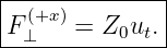
The answer is the characteristic mechanical wave impedance of the string.
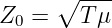
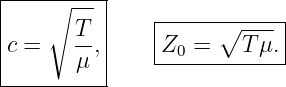
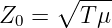
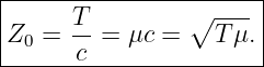
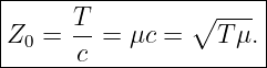
For an ideal string with Tension T, linear mass density μ, and wave speed
the characteristic impedance is
Its SI unit is
The impedance Z0 is a property of the medium and its tension. It tells us how transverse force and
transverse velocity are related for a one-way traveling wave [1, 2, 3, 6].
1 Mechanical impedance and characteristic impedance
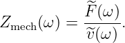
In vibration theory, a general mechanical impedance is often defined in harmonic steady state as a
ratio of force amplitude to velocity amplitude,
For a mass-spring-damper system or another reactive load, this quantity can depend on frequency
and can be complex.
A lossless uniform string has a particularly simple traveling-wave result. Its characteristic
impedance
is real and, within the ideal nondispersive string model, independent of frequency.
This article uses Z0 for that traveling-wave property. The ratio of force to velocity in an arbitrary
standing-wave field need not equal Z0 point by point.
2 Force and velocity at a cut in the string
Let u(x,t) be the transverse displacement. The local transverse velocity is
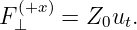
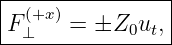
For small slopes, define the transverse force transmitted across a cut in the positive x direction
as
With this sign convention, the instantaneous power flowing in the positive x direction is exactly
the WM19 result
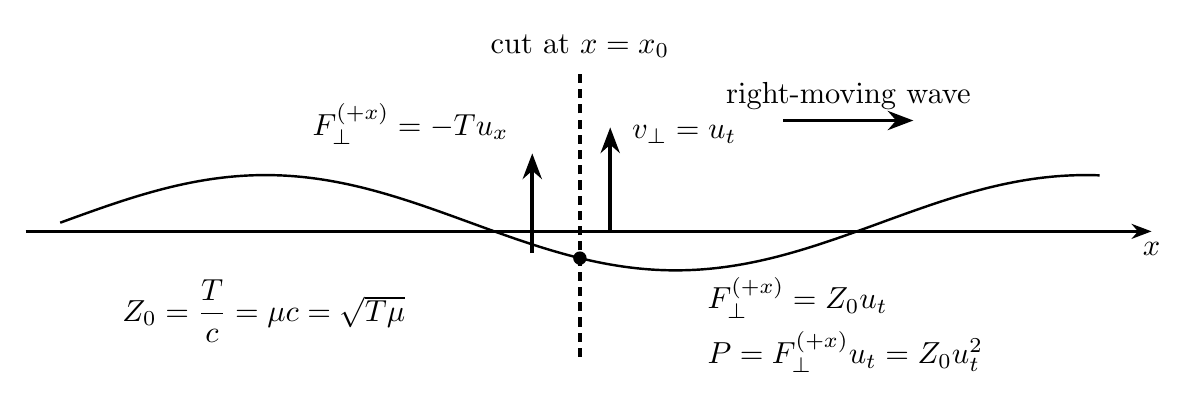
Figure. At a cut in the string, the traveling wave carries a transverse force and transverse
velocity. Their ratio defines the characteristic mechanical impedance for a one-way wave.
The sign convention is useful because positive P means energy transport toward increasing
x.
3 Right-moving wave: derive the impedance
For a right-moving profile
WM15 showed that
Therefore
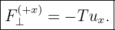
The transmitted transverse force becomes
| F⊥(+x) | = −Tu
x | (12)
|
| =  ut. ut. | (13) |
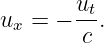
Define
Then a right-moving wave satisfies
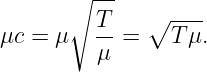
Because
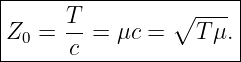
we may rewrite the impedance in two equivalent forms:
| Z0 | =  | (17)
|
| =  , , | (18) |
and
Thus
4 Left-moving wave and the sign of power
For a left-moving profile
we have
Hence
and
| F⊥(+x) | = −Tu
x | (24)
|
| = − ut ut | (25)
|
| = −Z0ut. | (26) |
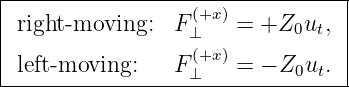
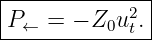
Therefore
The medium has the same positive characteristic impedance Z0 in either direction. The sign
change records the direction of power flow.
5 Power written in impedance form
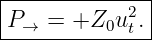
For a right-moving wave,
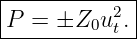
| P | = F⊥(+x)u
t | (28)
|
| = Z0ut2. | (29) |
Thus
For a left-moving wave,
This reproduces the directional power result from WM19 because
The impedance language therefore compresses the force, velocity, and power relations into a
compact set of equations.
6 Sinusoidal average power
Consider a right-moving sinusoidal wave
Its transverse velocity is
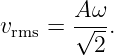
The RMS transverse velocity is
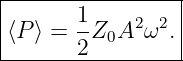
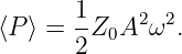
Averaging
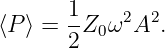
over one cycle gives
Equivalently,
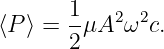
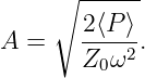
Since Z0 = μc, this is exactly the WM20 formula
This is the mechanical-wave analogue of the familiar statement that power depends on the
square of a wave amplitude multiplied by a characteristic impedance or admittance
factor.
7 How T and μ affect speed and impedance
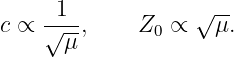
The speed and impedance depend differently on tension and linear density:
Thus increasing tension with μ fixed increases both c and Z0 as  .
.
Increasing linear density with T fixed has opposite effects on the two quantities:
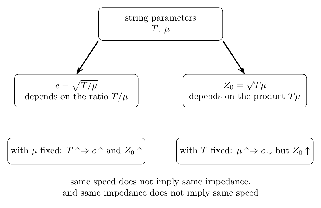
Figure. Wave speed depends on the ratio T∕μ, while characteristic impedance depends on
the product Tμ. Two strings can therefore have the same wave speed but different
impedances, or the same impedance but different wave speeds.
This distinction becomes central at an interface.
8 Why impedance matters at an interface
Suppose a harmonic wave traveling in medium 1 reaches an ideal junction with medium 2. Let the
characteristic impedances be
At an ideal massless junction, two conditions are imposed:
- the transverse displacement is continuous;
- the transverse force is continuous.
Write the incident, reflected, and transmitted displacement amplitudes as
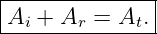
Displacement continuity gives
For harmonic waves, the transverse-force condition gives
The minus sign occurs because the reflected wave travels in the negative x direction.
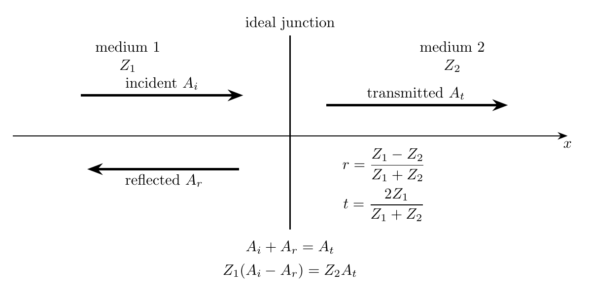
Figure. At an ideal interface, an incident wave generally produces both reflected and
transmitted waves. The relative impedances determine their amplitudes.
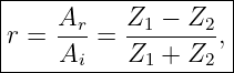
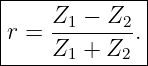
Solving the two equations gives the displacement-amplitude reflection coefficient
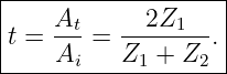
and the displacement-amplitude transmission coefficient
These formulas use the displacement-amplitude convention. Other wave variables can have
different amplitude-coefficient formulas even though the physical power balance is the same
[1, 2, 3].
9 Power reflection and transmission
For a harmonic traveling wave, the magnitude of the average power is
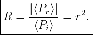
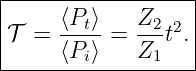
The fraction of incident power reflected is therefore
Using the transmitted amplitude coefficient t,
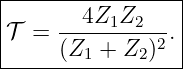
Substituting the expression for t gives
For a lossless ideal junction,
Note that t itself can exceed 1 without violating energy conservation. Power depends on both
amplitude and impedance.
10 Matched, fixed-like, and free-like limits
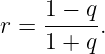
The reflection coefficient can be written in terms of the impedance ratio
as
Three limits are especially important.
Matched impedance
If
then
No reflected wave is required.
Very large terminating impedance
If
then
The displacement reflection is inverted, reproducing the fixed-end behavior introduced in
WM12.
Very small terminating impedance
If
then
The displacement reflection is not inverted, reproducing the free-end behavior.
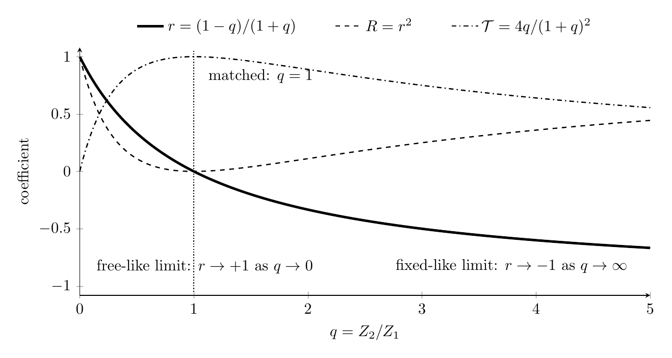
Figure. Displacement reflection coefficient r, reflected-power fraction R, and
transmitted-power fraction 𝒯 versus the impedance ratio q = Z2∕Z1. Perfect matching
occurs at q = 1.
Thus the fixed and free boundaries from WM12 can be understood as limiting cases of an
impedance mismatch.
11 Impedance matching does not require equal wave speed
A subtle but important point is that
depends on a ratio, while
depends on a product.
Therefore two media can satisfy
while still having
A harmonic wave can cross such an ideal matched interface without reflection even though its
wavelength changes because
The frequency remains fixed by the source while the wavelength adjusts to the new wave
speed.
12 Impedance across wave physics
The basic idea of impedance is broader than the string:
impedance relates a wave’s generalized effort variable to its generalized flow
variable.
For the string, these variables are transverse force and transverse velocity. In acoustics, a
characteristic impedance relates acoustic pressure to particle velocity. In Electromagnetism, wave
impedance relates electric and magnetic fields.
The formulas and units differ between physical systems, but the recurring ideas are the
same:
- a traveling medium has a characteristic relation between paired wave variables;
- that relation determines how much power a given amplitude transports;
- changes in characteristic impedance cause reflection;
- matching impedances suppresses reflection.
This is one reason the string is such a useful first model for later acoustic, optical, RF, and
transmission-line wave physics.
13 Worked Example 1: Compute characteristic impedance
An ideal string has
Find the wave speed and characteristic impedance.
Solution
The wave speed is
| c | =  | (67)
|
| =  m/s m/s | (68)
|
| = 100 m/s. | (69) |
The impedance is
| Z0 | = μc | (70)
|
| = (0.010)(100) kg/s | (71)
|
| = 1.00 kg/s. | (72) |
Thus
As a check,
14 Worked Example 2: Force and instantaneous power
A right-moving wave travels on a string with
At one instant and position, the transverse velocity is
Find the transverse force transmitted in the positive x direction and the instantaneous power.
Then repeat for a left-moving wave with the same local transverse velocity.
Solution
For the right-moving wave,
Therefore
The power is
Thus
For a left-moving wave,
and
The magnitude of the characteristic impedance is unchanged; the sign of the power identifies the
transport direction.
15 Worked Example 3: Average power from impedance
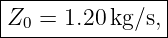
A string has
A right-moving sinusoid has amplitude
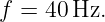
and frequency
Find Z0, the RMS transverse velocity, and the average power.
Solution
First,
The angular frequency is
With
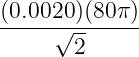
the RMS transverse velocity is
| vrms | =  | (89)
|
| =  m/s m/s | (90)
|
| ≃ 0.355 m/s. | (91) |
Then
| ⟨P⟩ | = Z0vrms2 | (92)
|
| = (1.20)(0.355)2 W | (93)
|
| ≃ 0.152 W. | (94) |
Therefore
This is the same numerical result obtained earlier from  μA2ω2c.
16 Worked Example 4: Required amplitude for a desired average power
A string has characteristic impedance
What displacement amplitude is required for a right-moving sinusoidal wave of frequency
to carry average power
Solution
Use
Solve for A:
The angular frequency is
Hence
| A | = 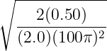 m m | (104)
|
| ≃ 2.25 × 10⁻³ m. | (105) |
Thus
17 Worked Example 5: Reflection from an impedance change
A sinusoidal wave travels from a string with
into a second string with
Find the displacement reflection coefficient, displacement transmission coefficient, reflected-power
fraction, and transmitted-power fraction.
Solution
The displacement reflection coefficient is
| r | =  | (109)
|
| =  | (110)
|
| = −0.60. | (111) |
The negative sign means the reflected displacement is inverted.
The displacement transmission coefficient is
| t | =  | (112)
|
| =  | (113)
|
| = 0.40. | (114) |
The reflected-power fraction is
The transmitted-power fraction is
| 𝒯 | = 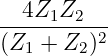 | (116)
|
| =  | (117)
|
| = 0.64. | (118) |
Thus
The power check is
18 Worked Example 6: Match impedances while changing wave speed
Medium 1 has
Medium 2 has tension
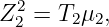
Choose μ2 so that the two characteristic impedances match. Then find both wave speeds.
Solution
For medium 1,
For matching,
Since
we need
| μ2 | =  | (127)
|
| =  kg/m kg/m | (128)
|
| = 5.625 × 10⁻³ kg/m. | (129) |
Thus
Now compute the speeds:
| c1 | =  | (131)
|
| = 90 m/s, | (132) |
while
| c2 | = 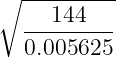 | (133)
|
| = 160 m/s. | (134) |
Therefore
The impedances match even though the wave speeds do not. An ideal harmonic wave can therefore
have zero reflection while its wavelength changes across the interface.
19 Common mistakes
- Mistake: confusing impedance with wave speed. For a string, c depends on T∕μ, while
Z0 depends on Tμ.
- Mistake: dropping the propagation-direction sign. Z0 is positive, but the force-velocity
relation changes sign between right- and left-moving waves under the chosen positive-x
convention.
- Mistake: using Z0 = F∕u instead of force divided by velocity. Mechanical impedance
pairs force with velocity.
- Mistake: applying the one-way relation F = Z0ut to an arbitrary Standing Wave.
That relation assumes a pure right-moving component.
- Mistake: treating the displacement transmission coefficient t as a power fraction.
Power transmission also depends on the impedance ratio.
- Mistake: assuming impedance matching requires equal wave speeds. Equal Z0 does
not imply equal c.
20 What WM22 adds to the wave-mechanics picture
The string-wave sequence now has a compact force-velocity transport relation:
For one-way waves,
and
For a sinusoid,
At an ideal interface,
Impedance therefore connects three ideas that were previously introduced separately:
This framework will later transfer naturally to acoustic and electromagnetic wave impedance. It
also prepares the way for characteristic impedance in transmission lines.
References
[1] A. P. French, Vibrations and Waves, M.I.T. Introductory Physics Series, W. W.
Norton & Company, 1971.
[2] Frank S. Crawford, Jr., Waves, Berkeley Physics Course, Volume 3, McGraw-Hill,
1968.
[3] Howard Georgi, The Physics of Waves, Prentice Hall, 1993.
[4] William Moebs, Samuel J. Ling, and Jeff Sanny, University Physics, Volume 1,
OpenStax, 2016, Section 16.4, “Energy and Power of a Wave.”
[5] William Moebs, Samuel J. Ling, and Jeff Sanny, University Physics, Volume 1,
OpenStax, 2016, Section 16.5, “Interference of Waves,” including reflection at boundaries.
[6] Massachusetts Institute of Technology, 8.03SC Physics III: Vibrations and Waves,
MIT OpenCourseWare, Fall 2016.


![|--------------------|
[Z0]-=-N-s∕m--=-kg∕s.-](https://images.physicslibrary.org/cache/objects/1191/make4ht/WaveMechanicsMechanicalWaveImpedance2x.png)