|
|
|
|||||||
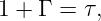
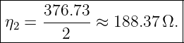
with, for lossless media,
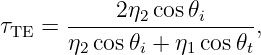
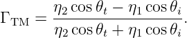
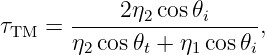
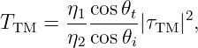
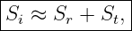
At oblique incidence the interface geometry matters, and TE and TM polarizations must be treated separately.
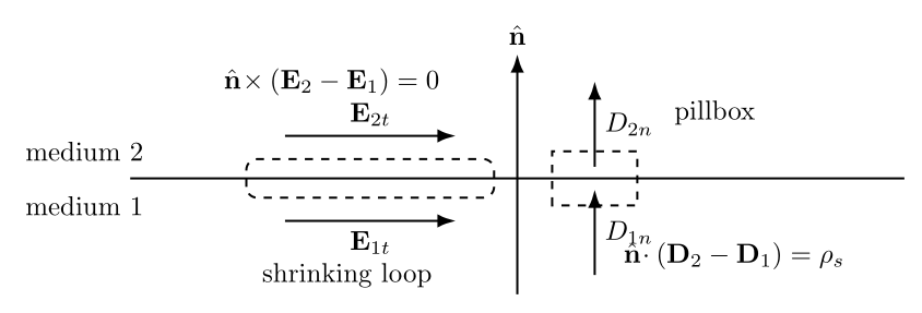
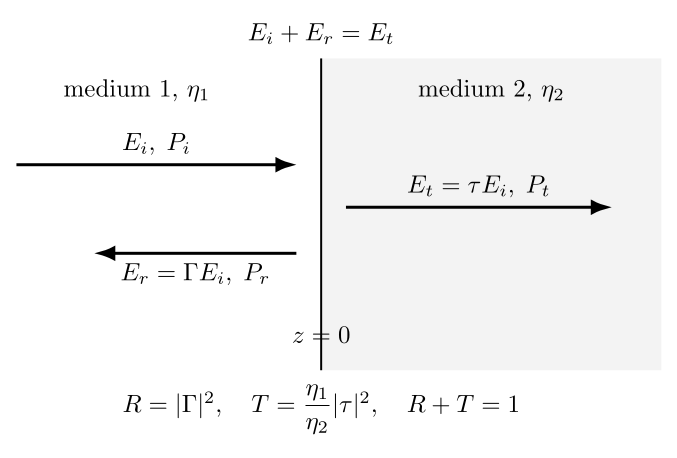
Figure 1. Boundary-condition bookkeeping. Tangential conditions come from shrinking loops; normal conditions come from pillboxes.
How to use this problem setAttempt the exercises in Part I before reading Part II. For every interface problem, proceed in the same order:
Part I: Exercises
Exercise 1: boundary conditions with surface charge and surface currentAn interface lies in the xy plane at z = 0, with unit normal n = z pointing from medium 1 into medium 2. The permittivities are
The normal electric field immediately below the interface is
and the free surface-charge density is
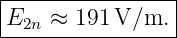
Find E2n. If in addition
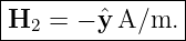
find the tangential magnetic field H2.
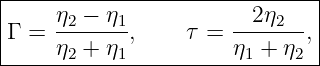
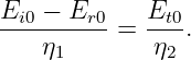
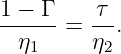
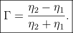
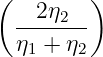
Exercise 2: derive the normal-incidence coefficientsFor a normally incident plane wave traveling from a lossless medium of impedance η1 into a lossless medium of impedance η2, derive
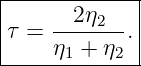
from continuity of tangential E and H. Show that
and verify that τ = 1 + Γ at normal incidence.
Exercise 3: air to a dielectric with 𝜖r = 4A 12 V/m sinusoidal plane wave in air strikes normally a lossless, nonmagnetic dielectric with 𝜖r = 4. Find
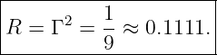
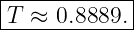
Exercise 4: dielectric to air and a transmitted field larger than the incident fieldReverse Exercise 3: a wave now travels normally from the 𝜖r = 4 dielectric into air. Compute Γ, τ, R, and T. Explain how |τ| > 1 can occur without violating conservation of energy.
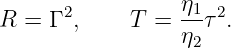
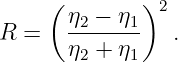
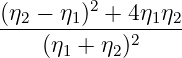
Exercise 5: prove normal-incidence power conservationStarting from
for real positive η1 and η2, prove algebraically that
where
Figure 2. At normal incidence, field amplitudes obey the boundary conditions while power conservation requires the impedance factor in T.
Exercise 6: Snell’s law from tangential phase matchingA plane wave travels from air, n1 = 1, into glass, n2 = 1.5, at an incidence angle
Using tangential phase matching, calculate the refraction angle 𝜃t. Also state the reflection angle.
Exercise 7: TE Fresnel coefficient at 45∘For air-to-glass incidence with n1 = 1, n2 = 1.5, μr1 = μr2 = 1, and
calculate
Verify numerically that RTE + TTE = 1.
Exercise 8: TM Fresnel coefficient at 45∘Repeat Exercise 7 for TM polarization. Compute
and compare the reflected power with the TE result.
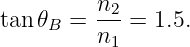
Exercise 9: Brewster angle and zero TM reflectionFor air-to-glass incidence with n1 = 1 and n2 = 1.5:
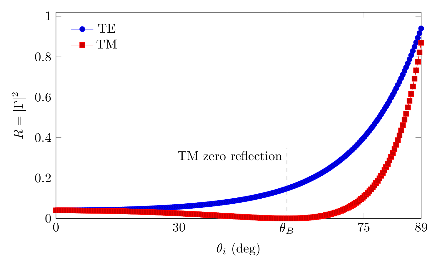
Figure 3. Air-to-glass Fresnel power reflectance. The TM curve crosses zero at the Brewster angle.
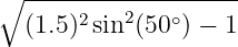
Exercise 10: critical angle from glass to airA wave travels from glass with n1 = 1.5 into air with n2 = 1. Find the critical angle. Classify the transmitted field for incidence angles of 30∘, 41.0∘, 41.81∘, and 50∘.
Exercise 11: total internal reflection and evanescent penetration depthA 10 GHz wave travels from a nonmagnetic dielectric with n1 = 1.5 into air at
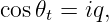
Show that the wave is above the critical angle. The tangential Wavenumber is conserved, and the normal wavenumber in air becomes imaginary:
with
Calculate the evanescent 1∕e penetration depth
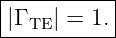
Also verify that the magnitude of the TE reflection coefficient is unity.
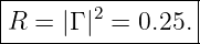
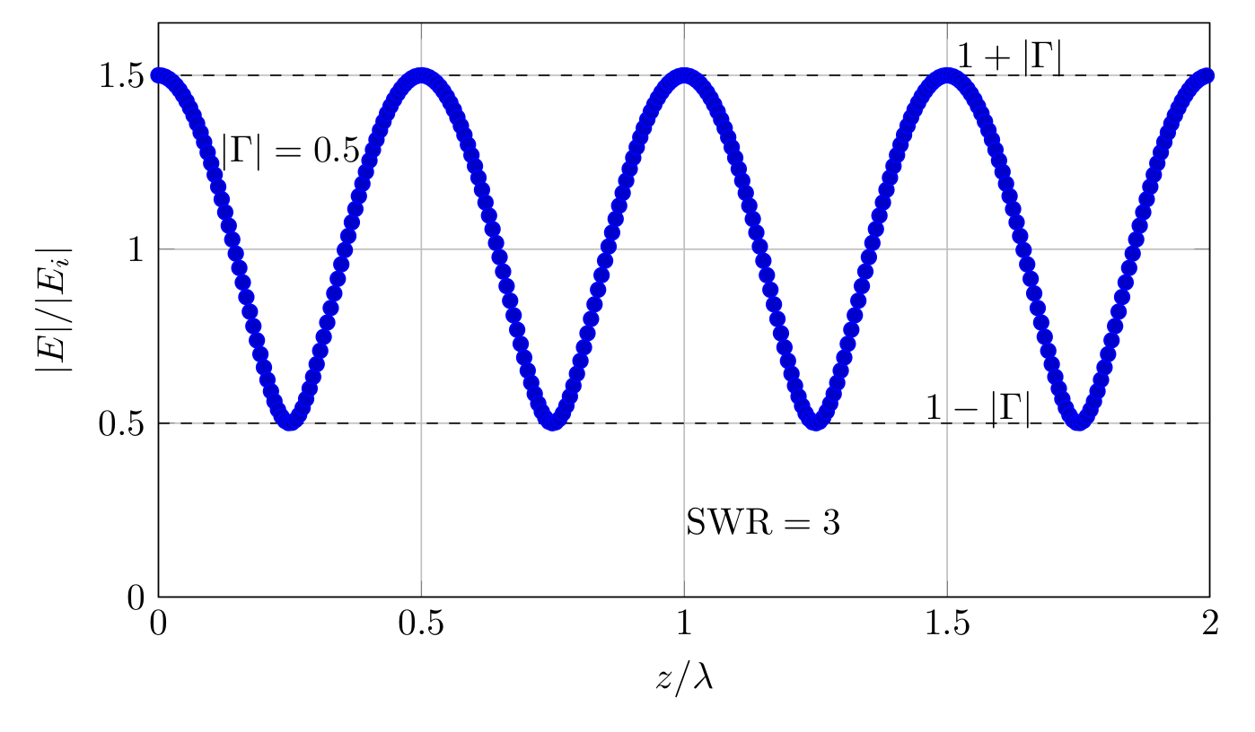
Exercise 12: SWR from a known reflection coefficientA lossless incident region has
Find the standing-wave ratio, the reflected power fraction, and the normalized field extrema |E|max∕|Ei| and |E|min∕|Ei|.
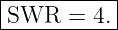
Exercise 13: infer reflection coefficient from SWRA measured standing-wave ratio is
Find |Γ| and the reflected power fraction R. If the incident electric-field amplitude is 10 V/m, find the maximum and minimum field magnitudes in the standing-wave pattern.
Figure 4. Standing-wave envelope for |Γ| = 0.5. The maxima and minima immediately reveal the SWR.
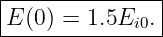
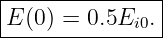
Exercise 14: phase reversal and standing-wave locationAt normal incidence, compare the two cases
At the interface z = 0, calculate the total electric-field amplitude relative to Ei0. Explain how the sign of Γ shifts a field maximum into a field minimum at the boundary.
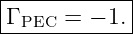
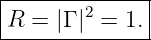
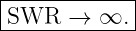
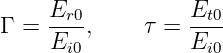
Exercise 15: perfect electric conductorA normally incident plane wave in free space strikes a perfect electric Conductor at z = 0. Derive
Show that the tangential electric field vanishes at the surface, the reflected power fraction is unity, and the magnetic field amplitude at the surface is twice the incident magnetic-field amplitude. What is the ideal SWR?
Exercise 16: Julia Fresnel and SWR sweepWrite a Julia program that, for a nonmagnetic air-to-glass interface with n1 = 1 and n2 = 1.5,
Part II: Complete Worked Solutions
Solution 1: boundary conditions with surface charge and surface currentThe normal electric-flux boundary condition is
Therefore
First,
Thus
Since D2n = 𝜖2E2n,
Hence
For the magnetic field,
Write the tangential jump as
Then
Matching components with 3x gives
Thus
Since H1 = 2y A/m,
The result demonstrates that surface charge controls the jump in normal D, while surface current controls the jump in tangential H.
Solution 2: derive the normal-incidence coefficientsAt the interface, tangential electric-field continuity gives
The magnetic fields satisfy
The minus sign belongs to the reflected magnetic field because the reflected Poynting vector points opposite to the incident one. Continuity of tangential H gives
Divide both equations by Ei0:
Substitute τ = 1 + Γ:
Therefore
so
Then
Thus
Solution 3: air to a dielectric with 𝜖r = 4For a nonmagnetic lossless dielectric,
Therefore
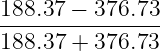
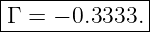
The reflection coefficient is
Hence
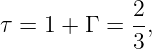
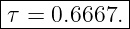
The negative sign means a 180∘ phase reversal of the reflected electric field. The transmission coefficient is
so
For Ei0 = 12 V/m,
The reflected power fraction is
The transmitted power fraction is
Thus
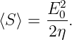
For a sinusoidal plane wave with peak electric-field amplitude E0,
Hence
Therefore
within rounding.
Solution 4: dielectric to air and a transmitted field larger than the incident fieldNow
Thus
so
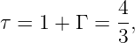
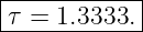
The transmission coefficient is
so
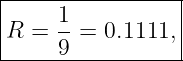
The power coefficients are
Thus
There is no energy paradox. The electric-field amplitude is larger in the higher-impedance medium, but power density scales as E02∕(2η). The impedance increase offsets the larger transmitted electric-field amplitude.
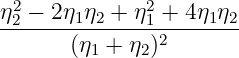
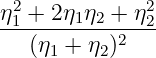
Solution 5: prove normal-incidence power conservationFor real impedances,
Also,
Therefore
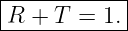
Hence
This is the boundary-wave statement of average power conservation for a lossless interface.
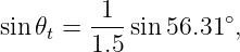
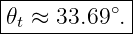
Solution 6: Snell’s law from tangential phase matchingTangential phase continuity gives
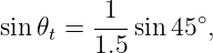
Thus
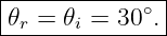
Therefore
The law of reflection gives
Solution 7: TE Fresnel coefficient at 45∘Snell’s law gives
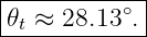
so
For nonmagnetic media,
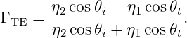
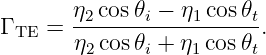
The TE reflection coefficient is
Substitution gives
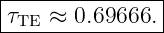
The TE transmission coefficient is
so
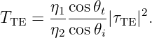
The reflected power fraction is
At oblique incidence,
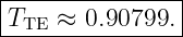
This gives
Therefore
Solution 8: TM Fresnel coefficient at 45∘The refraction angle is unchanged:
For TM polarization,
Hence
The electric-field transmission coefficient is
which gives
Then
The transmitted power fraction is
so
Again,
At 45∘, TM reflection is already much weaker than TE reflection because the incidence angle is approaching the Brewster angle.
Solution 9: Brewster angle and zero TM reflectionFor nonmagnetic lossless media,
Therefore
Snell’s law gives
which yields
Thus
For nonmagnetic media η ∝ 1∕n. The TM numerator is
At the Brewster geometry this vanishes, so
The absence of reflected TM power is therefore a direct boundary-condition result, not an independent empirical rule.
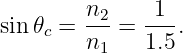
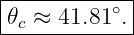
Solution 10: critical angle from glass to airFor incidence from the higher-index medium,
Hence
The cases are:
Solution 11: total internal reflection and evanescent penetration depthThe critical angle is
so 50∘ is above critical. At 10 GHz,
The evanescent decay constant is
Therefore
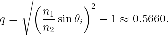
To verify total reflection, write
where
Insert this into
The numerator and denominator are complex conjugate in magnitude, giving
The phase is nonzero, so total internal reflection means unit reflected power, not necessarily Γ = +1 or −1.
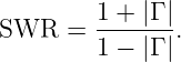
Solution 12: SWR from a known reflection coefficientThe standing-wave ratio is
Thus
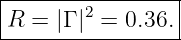
The reflected power fraction is
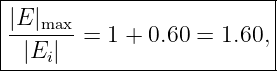
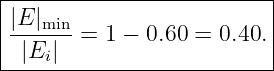
The normalized extrema are
Their ratio is 1.60∕0.40 = 4, as required.
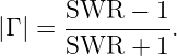
Solution 13: infer reflection coefficient from SWRInvert
Solving gives
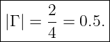
For SWR = 3,
Thus
If |Ei| = 10 V/m,
Solution 14: phase reversal and standing-wave locationAt z = 0,
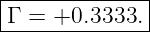
For Γ = +0.5,
This is the maximum envelope value because incident and reflected electric fields are in phase at the boundary. For Γ = −0.5,
This is the minimum envelope value because the reflected field is 180∘ out of phase with the incident field at the boundary. The magnitude |Γ| determines the ratio of maxima to minima, while the phase of Γ determines where those maxima and minima occur in space.
Solution 15: perfect electric conductorAt a PEC surface, the tangential electric field must vanish:
Therefore
so
The reflected power fraction is
No time-average power enters the ideal conductor. For the incident wave,
Because the reflected wave reverses propagation direction while also having Er0 = −Ei0, its magnetic field at the boundary points in the same tangential direction as Hi and has equal magnitude. Hence
The ideal electric-field Standing Wave has a zero minimum, so
Solution 16: Julia Fresnel and SWR sweepA compact Julia implementation is
using Printf

n1 = 1.0
n2 = 1.5
eta0 = 376.730313668
eta1 = eta0/n1
eta2 = eta0/n2

theta_deg = collect(range(0.0, 89.0, length=2001))
Rte = similar(theta_deg)
Rtm = similar(theta_deg)

for (i, deg) in enumerate(theta_deg)
    ti = deg2rad(deg)
    tt = asin((n1/n2)*sin(ti))

    rte = (eta2*cos(ti) - eta1*cos(tt)) /
          (eta2*cos(ti) + eta1*cos(tt))

    rtm = (eta2*cos(tt) - eta1*cos(ti)) /
          (eta2*cos(tt) + eta1*cos(ti))

    Rte[i] = abs2(rte)
    Rtm[i] = abs2(rtm)
end

imin = argmin(Rtm)
theta_B_num = theta_deg[imin]
theta_B_exact = rad2deg(atan(n2/n1))

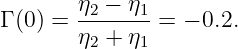
gamma0 = (eta2 - eta1)/(eta2 + eta1)
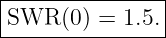
SWR0 = (1 + abs(gamma0))/(1 - abs(gamma0))

@printf("Numerical Brewster angle = %.4f deg\n", theta_B_num)
@printf("Analytic Brewster angle  = %.4f deg\n", theta_B_exact)
@printf("Normal-incidence Gamma    = %.6f\n", gamma0)
@printf("Normal-incidence SWR      = %.6f\n", SWR0)
For air to glass,
The numerical minimum should converge toward that value as the angular grid is refined. At normal incidence,
Therefore
Thus
The computational sweep is useful because it makes three landmarks visible at once: TE reflectance rises with angle, TM reflectance reaches zero at Brewster incidence, and both approach unity near grazing incidence.
Summary of the problem setThe calculations in EM21E1 can be organized around four layers:
The main practical cautions are:
These ideas form the direct mathematical bridge from free-space boundary waves to transmission lines, impedance matching, radomes, multilayer media, and RF hardware.
References
References
[1] D. J. Griffiths, Introduction to Electrodynamics, 4th ed., Cambridge University Press, 2017. [2] D. K. Cheng, Field and Wave Electromagnetics, 2nd ed., Addison-Wesley, 1989. [3] F. T. Ulaby and U. Ravaioli, Fundamentals of Applied Electromagnetics, 7th ed., Pearson, 2015. [4] C. A. Balanis, Advanced Engineering Electromagnetics, 2nd ed., Wiley, 2012. [5] D. M. Pozar, Microwave Engineering, 4th ed., Wiley, 2012. "Electromagnetic Waves, Antennas, and RF: Boundary Waves - Exercises and Complete Worked Solutions" is owned by bloftin.
This object's parent. Cross-references: transmission lines, Standing Wave, vector, charge, program, SWR, Conductor, boundary, magnitude, Wavenumber, Snell's law, glass, energy, average power, magnetic field, electric field, unit, impedance, TE polarization, Normal, parameters, TM polarizations, relations, Power, standing-wave ratio, total internal reflection, critical angle, Brewster angle, electromagnetic boundary conditions, EM21 There is 1 reference to this object. This is version 1 of Electromagnetic Waves, Antennas, and RF: Boundary Waves - Exercises and Complete Worked Solutions, born on 2026-10-09. Object id is 1446, canonical name is ElectromagneticWavesAntennasAndRFBoundaryWavesExercisesAndCompleteWorkedSolutions. Accessed 11 times total. Classification:
|
|
|
|
Pending Errata and AddendaNone.
|
DiscussionNo messages.
|
Interact |
![[parent]](https://images.physicslibrary.org/images/uparrow.png)














































 = 0
= 0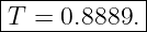



 sin 30
 (0
(0